MUTED – Biodata-Gehäuse für analoges Synthesizer-Modul
Originalquelle: https://wikifab.org/wiki/MUTED_-_boitier_biodata_vers_module_de_synth%C3%A9tiseur_analogique

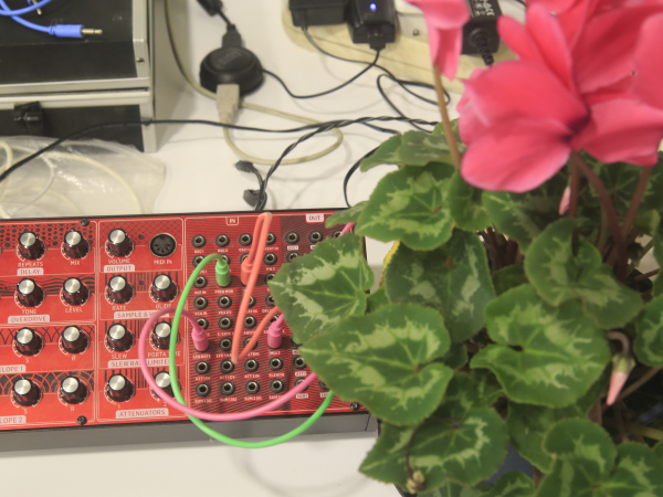
Gehäuse zum Anschluss einer Pflanze an einen analogen Synthesizer. Prototyp, der vom MUTED-Team während eines Hackathons zur Umwandlung von Biodaten in Musik entwickelt wurde, der Ende 2021 vom Climate Change Lab in Janzé in der Nähe von Rennes organisiert wurde.
Einführung
Dieser Prototyp wurde innerhalb von zwei Tagen in Janzé in der Nähe von Rennes vom MUTED-Team während eines Hackathons entwickelt, dessen Ziel es war, die in einer Pflanze festgestellte biologische Aktivität in eine musikalische Installation umzuwandeln. Um ihn nachzubauen, muss zunächst der im erforderlichen Tutorial beschriebene Sensor hergestellt werden.
Dann eine 3,5-mm-Klinkenbuchse zum Löten (oder aus einem alten Kopfhörerkabel) und eine Box zum Einbau des Geräts.
Achtung: Es funktioniert mit jedem Gerät, das eine Steuerspannung zwischen 0 und 3,3 V akzeptiert (insbesondere alle analogen Synthesizer).
Einleitungsvideo
Schritt 1 – Führen Sie zunächst das Tutorial Biodata-Sensor mit ESP32 durch.
Achtung: Sie müssen zunächst in der Lage sein, eine Pflanze an eine elektronische Karte anzuschließen, um winzige elektrische Schwankungen zu erfassen und umzuwandeln. Dies dauert zwischen zwei Stunden und einem halben Tag, wenn Sie dem Tutorial von Stéphane Godin folgen.
Schritt 2 – Arduino-Quellcode integrieren

Der kompatible Quellcode für den Betrieb des Sensors wird hier aufgerufen. Er muss kompiliert und mit dem Arduino-Tool an das ESP32-Modul gesendet werden.
/*
 MIT License

Copyright (c) 2016 electricityforprogress

Permission is hereby granted, free of charge, to any person obtaining a copy
of this software and associated documentation files (the "Software"), to deal
in the Software without restriction, including without limitation the rights
to use, copy, modify, merge, publish, distribute, sublicense, and/or sell
copies of the Software, and to permit persons to whom the Software is
furnished to do so, subject to the following conditions:

The above copyright notice and this permission notice shall be included in all
copies or substantial portions of the Software.

THE SOFTWARE IS PROVIDED "AS IS", WITHOUT WARRANTY OF ANY KIND, EXPRESS OR
IMPLIED, INCLUDING BUT NOT LIMITED TO THE WARRANTIES OF MERCHANTABILITY,
FITNESS FOR A PARTICULAR PURPOSE AND NONINFRINGEMENT. IN NO EVENT SHALL THE
AUTHORS OR COPYRIGHT HOLDERS BE LIABLE FOR ANY CLAIM, DAMAGES OR OTHER
LIABILITY, WHETHER IN AN ACTION OF CONTRACT, TORT OR OTHERWISE, ARISING FROM,
OUT OF OR IN CONNECTION WITH THE SOFTWARE OR THE USE OR OTHER DEALINGS IN THE
SOFTWARE.


This project is based on https://github.com/electricityforprogress/MIDIsprout great work about biodata sonification
*/

#include <Arduino.h>

#define SAMPLESIZE  32
#define LED 5
#define DAC1 25

#define DESIRED_EVENT 6
#define ARRAYLEN(a) ((sizeof(a))/(sizeof(a[0])))

//manage LEDs without delay() jgillick/arduino-LEDFader https://github.com/jgillick/arduino-LEDFader.git
void sample();
float mapfloat(float x, float in_min, float in_max, float out_min, float out_max);
void analyzeSample();


//******************************
static byte state;
//*******************************

const byte interruptPin = 12; //galvanometer input

byte samplesize = SAMPLESIZE / 2; //set sample array size
//const byte analysize = SAMPLESIZE - 1;  //trim for analysis array


int CVmod = 0;


volatile unsigned long microseconds; //sampling timer
volatile byte sindex = 0;
volatile unsigned long samples[SAMPLESIZE];

float threshold = 1;  //change threshold multiplier


unsigned long previousMillis = 0;
unsigned long currentMillis = 1;
unsigned long batteryCheck = 0; //battery check delay timer

uint32_t threshold_last_millis = 0;
unsigned int  threshold_evt = 0;


//std::vector<CSequence*> psequences;

uint32_t sequence_time = 0;
uint16_t sequence_index = 0;
uint32_t chipId = 0;

char bleserverid[64] = "";
void setup()
{

  for(int i=0; i<17; i=i+8) {
    chipId |= ((ESP.getEfuseMac() >> (40 - i)) & 0xff) << i;
  }


  pinMode (LED, OUTPUT);    // initilize led output
  digitalWrite(LED, HIGH);   // set led ON

  sprintf (bleserverid, "BioData_%08lx MIDI device", chipId);
 // BLEMidiServer.begin(bleserverid); // initialize bluetooth midi
  Serial.begin(115200);                       //initialize Serial for debug


  attachInterrupt(interruptPin, sample, RISING);  //begin sampling data from interrupt

}

void loop()
{
  currentMillis = millis();   //manage time

  if(sindex >= samplesize)  { analyzeSample(); }  //if samples array full, also checked in analyzeSample(), call sample analysis


  if (currentMillis - threshold_last_millis > 15000)
  {

      if (threshold_evt < DESIRED_EVENT)
      {
        if (threshold > 0.001)
          threshold /= 1.4;
      }
      else
      {
        if (threshold < 10)
          threshold *= 1.4;
      }
      threshold_last_millis = currentMillis;
      threshold_evt = 0;
      //Serial.println(threshold);
  }


}


//interrupt timing sample array
void sample()
{
  if(sindex < samplesize) {
    samples[sindex] = micros() - microseconds;
    microseconds = samples[sindex] + microseconds; //rebuild micros() value w/o recalling
    //micros() is very slow
    //try a higher precision counter
    //samples[sindex] = ((timer0_overflow_count << 8) + TCNT0) - microseconds;
    sindex += 1;
  }
  digitalWrite(LED, ((state) & 0x01) == 0 ? HIGH : LOW);
  state++;


}


void analyzeSample()
{

  //eating up memory, one long at a time!
  unsigned long averg = 0;
  unsigned long maxim = 0;
  unsigned long minim = 10000000;
  float stdevi = 0;
  unsigned long delta = 0;
  byte change = 0;

   digitalWrite(LED, ((state) & 0x01) == 0 ? HIGH : LOW);
  state++;
  if (sindex >= samplesize) { //array is full
    unsigned long sampanalysis[SAMPLESIZE];
    for (byte i=0; i < samplesize; i++){
      //skip first element in the array
      sampanalysis[i] = samples[i];  //load analysis table (due to volitle)
      //manual calculation
      if(sampanalysis[i] > maxim) { maxim = sampanalysis[i]; }
      if(sampanalysis[i] < minim) { minim = sampanalysis[i]; }
      averg += sampanalysis[i];

    }
    averg = averg / (samplesize);
    for (byte i = 0; i < samplesize; i++)
    {
      stdevi += (sampanalysis[i] - averg) * (sampanalysis[i] - averg) ;  //prep stdevi
    }

    //manual calculation

    stdevi = stdevi / (samplesize);
    if (stdevi < 1) { stdevi = 1.0; } //min stdevi of 1

    stdevi = sqrt(stdevi); //calculate stdevu

    delta = maxim - minim;


    //Serial.printf("%ld %ld %ld %ld %f %f\r\n", minim, maxim, averg, delta, stdevi, stdevi * threshold);
    Serial.printf("%ld", delta);
    //Serial.print(averg);
    Serial.println(",");
    CVmod = map(delta, 0, 20000, 0, 255);
    Serial.println(CVmod);

    int data2 = delta % 255;
    Serial.println(data2);
    dacWrite(DAC1, data2);

    sindex = 0;

  }
}
Schritt 3 – Anschlüsse überprüfen
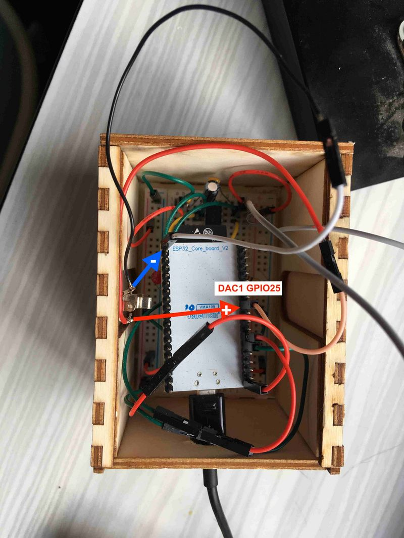
Die Masse Ihres Audiokabels muss an den GND-Pin des ESP32 angeschlossen werden.
Der andere Draht muss an den GPIO-Pin 25 angeschlossen werden. Das Modul verfügt nämlich über zwei Pins, die automatisch die Umwandlung „Digital Analogic Converter” vornehmen, die Pins GPIO 25 und 26. Dies geschieht in einem Bereich zwischen 0 und 3,3 V.
Um die Funktion zu testen, können Sie ein Multimeter nehmen und es an zwei Abschnitten des Klinkensteckers anlegen. Normalerweise messen Sie eine variable Spannung zwischen 0 und 3,3 V.
Schritt 4 – Das Modul an einen Synthesizer anschließen
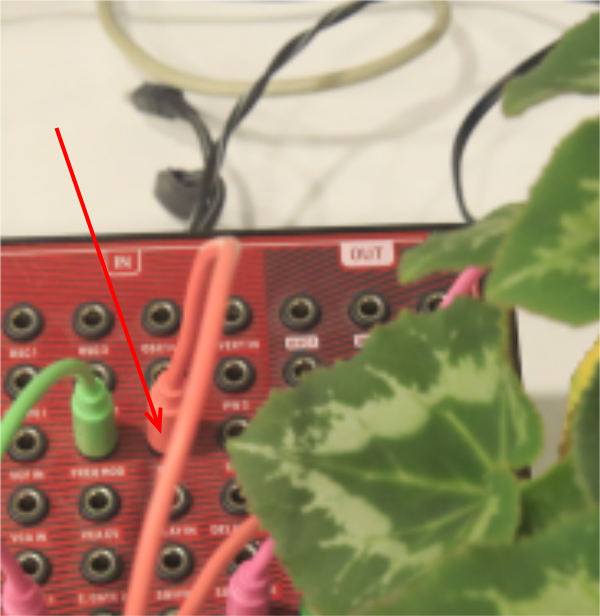
Jetzt müssen Sie nur noch das an eine Pflanze angeschlossene Gehäuse mit Strom versorgen (zwei abisolierte Kabel an zwei Stäben) und den Stecker einstecken, um ein lebendes Modul in Ihren Synthesizer zu integrieren.
Ein großes Dankeschön an Simon Lamy für die bereitgestellten Informationen und die Medienelemente dieses Tutorials!
Notizen und Referenzen
- Biodata/Sound/Beispiele: https://electricityforprogress.com/biodata-sonification
- Mehrere Ressourcen Labomedia: https://ressources.labomedia.org/capteurs_environnementaux_biofeedback
- Midi + Arduino: http://www.planetarduino.org/?cat=5499
- MIDI/Noten: https://newt.phys.unsw.edu.au/jw/notes.html
- Midi-Paket-Logger: http://www.midiox.com
Keine Kommentare vorhanden
Keine Kommentare vorhanden