Raspberry Pi 3 B - GPIO config
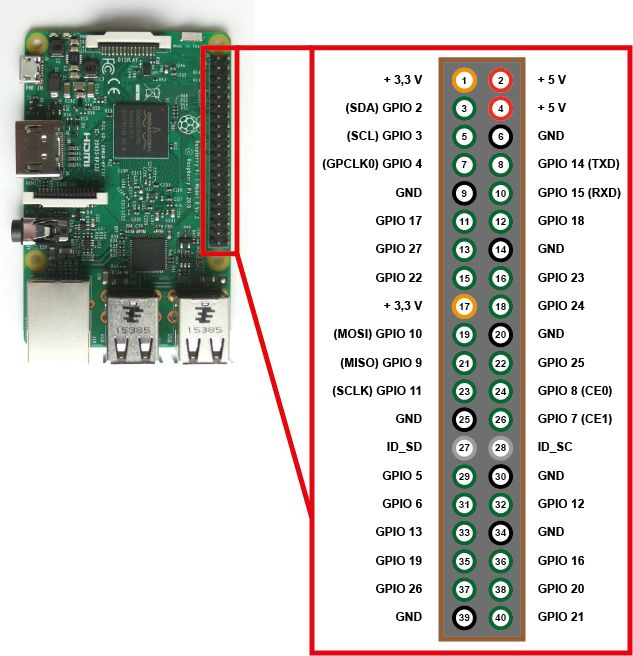
GPIO (General Purpose Input/Output) pins on the Raspberry Pi
https://www.raspberrypi.org/documentation/hardware/raspberrypi/gpio/README.md
GPIO pins - also called General Purpose Input Output - are the central interface between the Raspberry Pi to external devices and digital circuits. In addition to simple control, certain pins also perform certain functions such as communication via I2C, UART or SPI.
Overview
This page expands on the technical features of the GPIO pins available on BCM2835 in general. For usage examples, see GPIO usage . When reading this page, reference should be made to the BCM2835 ARM peripherals data sheet, section 6. GPIO pins can be configured as either general-purpose input, general-purpose output, or as one of up to six special alternate settings, the functions of which are pin-dependent. There are three GPIO banks on BCM2835. Each of the three banks has its own VDD input pin. On Raspberry Pi, all GPIO banks are supplied from 3.3V. Connection of a GPIO to a voltage higher than 3.3V will likely destroy the GPIO block within the SoC. A selection of pins from Bank 0 is available on the P1 header on Raspberry Pi.
GPIO pads
The GPIO connections on the BCM2835 package are sometimes referred to in the peripherals data sheet as "pads" — a semiconductor design term meaning 'chip connection to outside world'. The pads are configurable CMOS push-pull output drivers/input buffers. Register-based control settings are available for:
- Internal pull-up / pull-down enable/disable
- Output drive strength
- Input Schmitt-trigger filtering
Power-on states
All GPIO pins revert to general-purpose inputs on power-on reset. The default pull states are also applied, which are detailed in the alternate function table in the ARM peripherals datasheet. Most GPIOs have a default pull applied.
Interrupts
Each GPIO pin, when configured as a general-purpose input, can be configured as an interrupt source to the ARM. Several interrupt generation sources are configurable:
- Level-sensitive (high/low)
- Rising/falling edge
- Asynchronous rising/falling edge
Level interrupts maintain the interrupt status until the level has been cleared by system software (e.g. by servicing the attached peripheral generating the interrupt). The normal rising/falling edge detection has a small amount of synchronisation built into the detection. At the system clock frequency, the pin is sampled with the criteria for generation of an interrupt being a stable transition within a three-cycle window, i.e. a record of '1 0 0' or '0 1 1'. Asynchronous detection bypasses this synchronisation to enable the detection of very narrow events.
Alternative functions
Almost all of the GPIO pins have alternative functions. Peripheral blocks internal to BCM2835 can be selected to appear on one or more of a set of GPIO pins, for example the I2C busses can be configured to at least 3 separate locations. Pad control, such as drive strength or Schmitt filtering, still applies when the pin is configured as an alternate function.
Voltage specifications
The following table gives the various voltage specifications for the GPIO pins, it was extracted from the Compute Module datasheet here.
| Symbol | Parameter | Conditions | Min | Typical | Max | Unit |
| VIL | Input Low Voltage | VDD IO = 1.8V | - | - | 0.6 | V |
| VDD IO = 2.7V | - | - | 0.8 | V | ||
| VDD IO = 3.3V | - | - | 0.9 | V | ||
| VIH | Input high voltagea | VDD IO = 1.8V | 1.0 | - | - | V |
| VDD IO = 2.7V | 1.3 | - | - | V | ||
| VDD IO = 3.3V | 1.6 | - | - | V | ||
| IIL | Input leakage current | TA = +85◦C | - | - | 5 | µA |
| CIN | Input capacitance | - | - | 5 | - | pF |
| VOL | Output low voltageb | VDD IO = 1.8V, IOL = -2mA | - | - | 0.2 | V |
| VDD IO = 2.7V, IOL = -2mA | - | - | 0.15 | V | ||
| VDD IO = 3.3V, IOL = -2mA | - | - | 0.14 | V | ||
| VOH | Output high voltageb | VDD IO = 1.8V, IOH = 2mA | 1.6 | - | - | V |
| VDD IO = 2.7V, IOH = 2mA | 2.5 | - | - | V | ||
| VDD IO = 3.3V, IOH = 2mA | 3.0 | - | - | V | ||
| IOL | Output low currentc | VDD IO = 1.8V, VO = 0.4V | 12 | - | - | mA |
| VDD IO = 2.7V, VO = 0.4V | 17 | - | - | mA | ||
| VDD IO = 3.3V, VO = 0.4V | 18 | - | - | mA | ||
| IOH | Output high currentc | VDD IO = 1.8V, VO = 1.4V | 10 | - | - | mA |
| VDD IO = 2.7V, VO = 2.3V | 16 | - | - | mA | ||
| VDD IO = 3.3V, VO = 2.3V | 17 | - | - | mA | ||
| RPU | Pullup resistor | - | 50 | - | 65 | kΩ |
| RPD | Pulldown resistor | - | 50 | - | 65 | kΩ |
a Hysteresis enabled
b Default drive strength (8mA)
c Maximum drive strength (16mA)
wiringPi and GPIO connection overview
max. allowed power consumption for GPIO in total is 50 mA and a maximum of 16 mA per pin
| Device | Consumption | Notes | wiringPi / GPIO commands for connected devices |
| Gyroscope and acceleration sensor GY-521 (MPU6050) @ 3.3V |
|
|
|
| Inertial Measurement Unit MPU 9250 / GY-250 InvenSense @ 3.3V | ? |
|
|
| Relay JQC-3FF-S-Z @ 5V |
|
Way 1 (preferred)
Use the scripts Way 2 Way 3 Failed Status |
|
| Filament sensing with KY-040 Rotary Encoder | ? | Encoder for filament monitor on extruder and for switchting into manual torque mode |
Have a look at |
| Relay JQC3F-05VDC-C |
|
Relay to switch on/off center LED spot |
There's a sepcial abusing python script for this because the relay has a logic level issue with Raspberry Pi (voltage differences) → See https://raspberrypi.stackexchange.com
pip3.7 install RPi.GPIO
Use the scripts Failed Status |
wiringPi GPIO and pintest utility
pintest: this is to check the pins at onc
Install wiringPi
apt install wiringpiGet pintest
Install this tool manually because the the apt repo for wiringPi does not contain the utility "pintest".
#install wiringPi manually because the apt repo does not contain the utility "pintest" ...
cd
#git clone git://git.drogon.net/wiringPi #failed due to offline state
git clone https://github.com/WiringPi/WiringPi.git
cd ~/WiringPi
./build
cd ~/WiringPi/gpio
chmod +x pintest
./pintest
Review the result
PinTest
=======

This is a simple utility to test the GPIO pins on your Raspberry Pi.

NOTE: All GPIO peripherals must be removed to perform this test. This
  includes serial, I2C and SPI connections. You may get incorrect results
  if something is connected and it interferes with the test.

This test can only test the input side of things. It uses the internal
pull-up and pull-down resistors to simulate inputs. It does not test
the output drivers.

You will need to reboot your Pi after this test if you wish to use the
serial port as it will be left in GPIO mode rather than serial mode.

This test only tests the original pins present on the Rev A and B. It
does not test the extra pins on the Revision A2, B2 nor the A+ or B+

Please make sure everything is removed and press the ENTER key to continue,
or Control-C to abort...

          The main 8 GPIO pins  0: 7:  OK
                The 5 SPI pins 10:14:  OK
               The serial pins 15:16:  OK
The I2C pins 8: 9: OKrebootHelpful commands
gpio readall
gpio exports #list all exported pin (also lists pins which were not exported with the GPIO tool itself)
Bash commands
This was not tested yet!
#unexport GPIO pins without external tools or libraries
sudo bash -c "for ((i=0; i<32; i++)); do echo \$i; echo in >/sys/class/gpio/gpio\$i/direction; echo \$i >/sys/class
/gpio/unexport; done"