Building basics, checks, maintenance
This guide only fits for Trikarus or Hangprinters which make use of RepRapFirmware and closed loop motors with implemented torque mode feature. If you have no closed loop motors, no torque mode or if you run Marlin those procedures are different (other ways of measuring anchor points, coordinate system buildup, G-Codes, ...). So please check if the firmware (fork) you use has the according features. Ignoring will result in strange results or just zero results. The guide tries to focus on the core parts which are ceiling module, effector, print platform and anchors. The short answer for what you have to do: get everything level (especially the horizontal direction), free of tilts and tighten the lines. Driven by concept a real Hangprinter might not have the fancy regular frame Trikarus has. It's not easy to say how long the procedure described at this page takes. Take hours into account! Only setting up the frame will take 40 - 60 minutes. Inserting all the components and fixing them has a lot of frustration potential.
You have to do an intense calibration after mounting your anchors in the room / frame because the firmware needs to know the XYZ position of each anchor. There are 4 general anchor points for 4 axes ABCD in total. Because there are 9 lines in total there are 9 places where the lines need to be fixed (knots) and tuned. An uncalibrated Hangprinter will never reach the targeted coordinates properly. Either it will try to move too far out of the volume (which is not possible) or it just will never reach the maximum possible volume - depending on the values you measured and entered. A bad calibrated printer will behave just not as exspected. For example if you set the effector to home position and let it move to some XY with keeping Z coordinate constant it may happen that the effector still lifts up or down, which means it does not keep the Z level constant. That means that you cannot print anything.
General overview
Please have a look at Typical Hangprinter problems to have an overview of bad things which can happen with Hangprinters in general.
The following illustration shows the general concept of Trikarus, reduced to some core components.
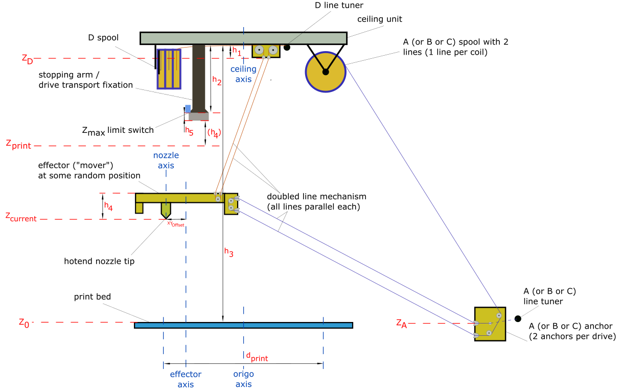
- $h_1 = 32 mm$ (effective height of the D line ceiling anchors)
- $h_2 = 190 mm$ (height where mover will "sit" in the three arm pockets (usually for parking or transport fixation)
- $h_4 = 63.5 mm$ (height from effective effector D line entries to nozzle tip)
- $h_5 = 15.08 mm$ (height of the arm borders - remember that the effector can not properly move if it is countersunk into the arms)
- $d_{print} = 1000 mm$ (value bounded by the developed print platform). See also Building basics, checks, maintenance or thumb formula for recommended print diameter)
Unknown variables of Trikarus to find out by measuring and calibrating
- $Z_{print}$ (maximum printing height - required for slicing. This will vary according to your frame size)
- $d_{print}$ (maximum printing diameter - required for slicing. This will vary according to your frame size)
- $ \vec{Z_A} = \begin{bmatrix} X_A\\ Y_A\\ Z_A \end{bmatrix}$ (A anchor point)
- $ \vec{Z_B} = \begin{bmatrix} X_B\\ Y_B\\ Z_B \end{bmatrix}$ (B anchor point)
- $ \vec{Z_C} = \begin{bmatrix} X_C\\ Y_C\\ Z_C \end{bmatrix}$ (C anchor point)
- $\vec{Z_D} = \begin{bmatrix} X_D\\ Y_D\\ Z_D \end{bmatrix}$ (D anchor point)
- $XY_{Offset}$ (the axis offset between the nozzle axis and effector axis)
Notes on the scheme above
- only 1 of 3 drives ABC with one line shown
- only 1 of 3 lines of D drive shown
- only 1 of 3 stopping arms / drive fixations shown
- only 1 of 3 line tuners shown
- belonging to the height difference between your print platform and your ABC anchors the Z height per anchor might be a positive or negative value each. All anchors have a unique Z value because the floor / bottom frame will not be exactly horizontal. The six bottom anchors settle the pivot points ABC.
- $Z_{max} = h_3 - h_2 - h_4 - h_5 - h_{buffer}$ is machine specific value which requires to set $Z_{max}$ size correctly in firmware and slicer profile (remember: usually Hangprinters do not have any limit switch. Trikarus tries to implement a height switch for $Z_{max}$ but it's experimental). Note that $h_5$ is the height of the profile pocket where effector will sit in. The effector cannot move if it is caged, so you will have to reduce height effectively by this value. Additionally it makes sense to add some buffer (safety distance) between mover and $Z_{max}$. You should use some value$h_{buffer} > 5 mm$
- $h_3$ depends on the calibration itself. For example if a +50 mm move in Z direction only moves +40 mm, $h_3$ and therefore $Z_{print}$ and $Z_{max}$ will be horribly wrong
- $d_{print}$ needs to be be tested for each new room / frame because larger anchor distances mean larger print diameter
-
pivot point $Z_D = h_3 - h_1$ can be measured manully with a laser distance meter (measure the total height from bed to ceiling plate and subtract $h_1$) or just calculate it by
$$Z_D = Z_{max} + h_2 - h_1$$
$$= Z_{max} + 190 mm - 32 mm$$
$$= Z_{max} + 158 mm$$
$$= Z_{print} + h_5 + h_4 + h_2 - h_1$$
$$= Z_{print} + 15.08 mm + 63.5 mm + 190 mm - 32 mm$$
$$= Z_{print} + 236.58 mm$$ -
pivot points $Z_A$, $Z_B$, $Z_C$ can be measured with linear ruler or similar
- $Z_0$ is where the top side of print bed including print surface (like blue tape) is
- $XY_{Offset}$ is a required value for offset between nozzle axis and effector axis to define the tool position
- Basically there are different axes which could be the Z axis of the origin coordinate system, for example the axis of the nozzle, the center of the effector triangle, the center of the print platform (if it has some kind of center - maybe your print platform is just some random piece of wood) or the center of your ceiling plate (center of the triangle which is formed by the three D lines) or the middle of your frame. We use the ceiling axis as origin axis. The ceiling axis can be understood as some kind of "root axis" because it's spawned by the center of the three D lines. And as we already did some pre-matching adjustments while setting up the machine, we can say roughly that nozzle axis, effector axis, ceiling axis and bed axis and frame axis are aligned on each other.
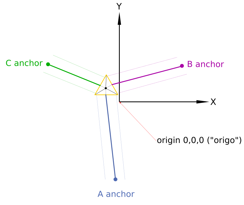
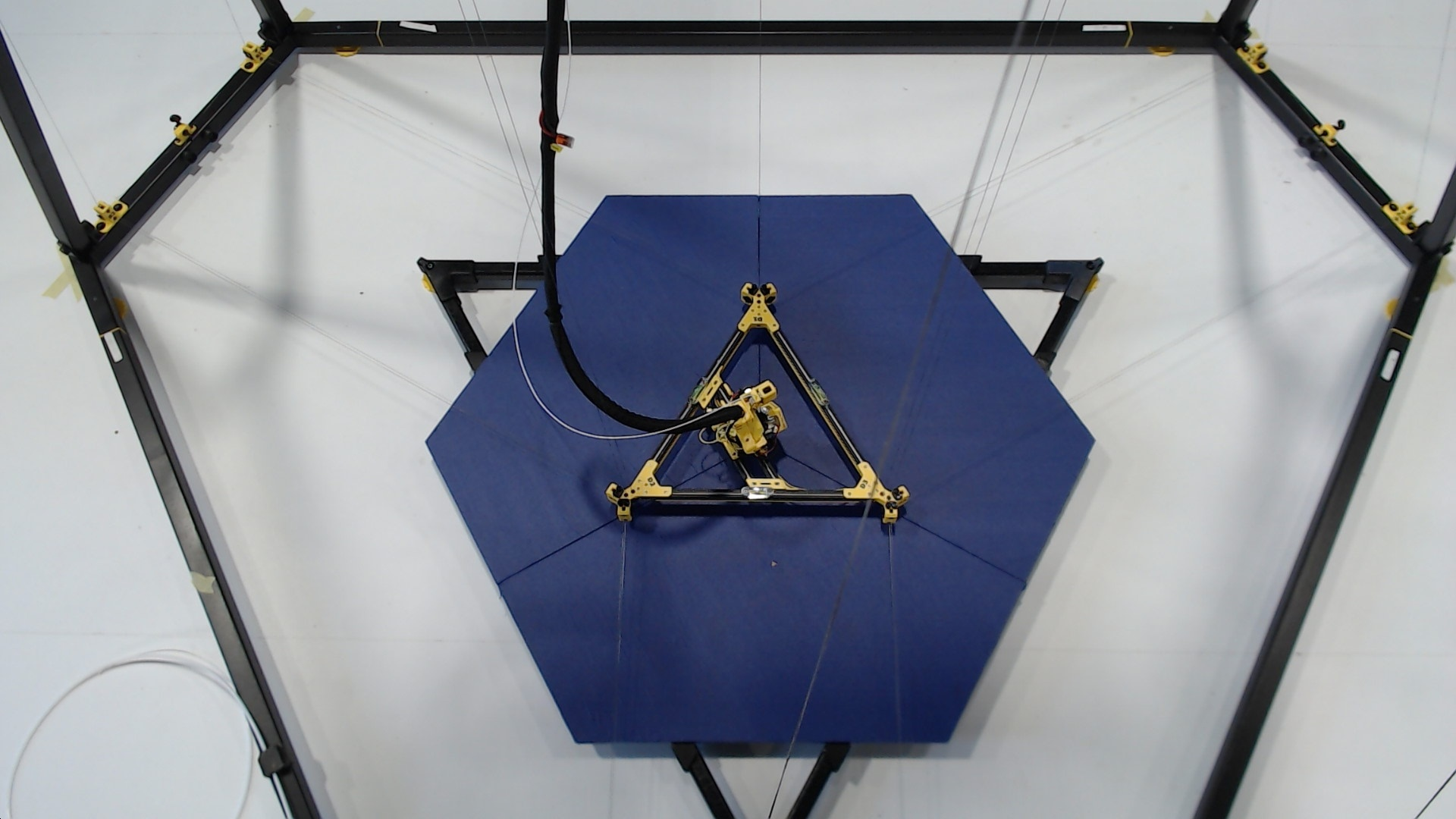
- the coordinate system (origin X0 Y0 Z0) is where the nozzle tip touches the print bed. It is aligned as shown in the following image (X axis perpendicular to to the line the A anchors form, B and C are kind of mirrored each other to Y axis). Another description: A lines are always parallel to Y axis (X- quarters). B anchor points are in X+/Y+ quarter and C anchor points are in X-/Y+ quarter.
- for calibration and verification purposes there are different types of anchor coordinates. There are pivot points A, B and C anchor coordinates, as well as explicite A1/A2, B1/B2 and C1/C2 anchor coordinates. The explicite A1/A2, B1/B2 and C1/C2 anchor coordinates can be used for print volume verification OpenSCAD tool.
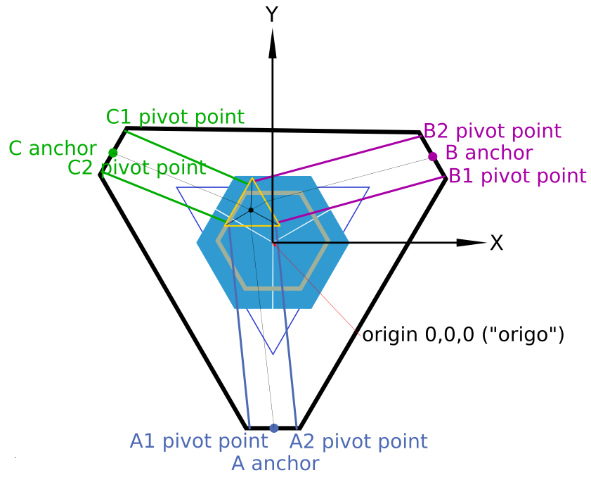
Note that in this drawing the print platform is not centered perfectly like you will have in a real world situation too. The image also shows the effector at some random position to better clarify for the parallelism of each line pair A, B and C.
Required tools for building and calibrating
- computer with network access and all required software stuff → Building basics, checks, maintenance
- grease gun (for sure with grease inside)
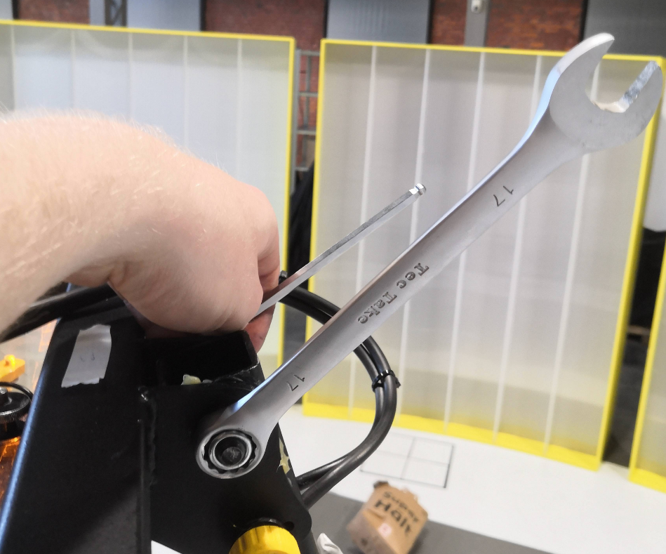
- set of metric hex keys (standard sizes from 2 up to 10 mm) - this is really important
- set of open jaw wrenches - this is really important
- adjustable jaw wrench (there are a lot of parts which have a hexagon socket to keep fixed)
- pipe wrench
- rubber hammer
- marking
- permanent marker - thick
- permanent marker - thin
- masking tape (for temporary markings at the floor and elsewhere)
- elektronic labeleling device (if you don't label your things it will be your death)
- spare parts
- screws
- fireline
- other components which might belong to Hangprinter
- measurement things
- tape measure
- carpenter's rule
- caliper
- multimeter
- cross spirit level (used for the print platform)
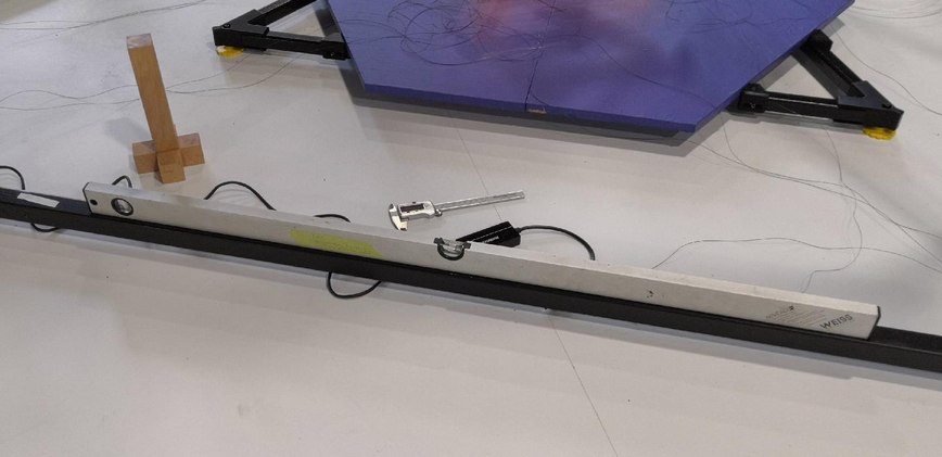
- regular long shape bubble level (used for the base frame - don't use a crappy lightweight one and check if the spirit levels are correctly adjusted inside their housing)
- laser distance meter- this is really important
- marble or ball (for checking levelness of the ground)
- cutter knife
- thermal paste
- tweezers or some individual bent paperclip (for picking up the lines or pulling out SD cards from Raspi / Duet)
- piece of cloth (for cleaning and handling a really hot nozzle)
-
screw driver cross recess - rough
-
screw driver cross recess - fine
-
screw driver single recess - fine (for screwing down the terminals of Duet and Smart Stepper)
- a ladder to reach the top of the frame - this is really important
- roller or squeegee (for applying blue tape)
Other highly recommended stuff
- access to a good high-output coffee machine
- much much much much much time. It's not something you just do on the side while being in a hurry.
- endurance
- quiet people who don't bug you
Transporting Trikarus and pre-preparations
Effector fixation and bottom anchor line wiring
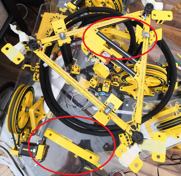
- lock the aluminum beams with three velcro strips at the arms. Note that the velcro clips are only for transportation and not for daily use! Using them for regular parking of the effector is not very handy. Brakes for each drive would be a better idea for this job.
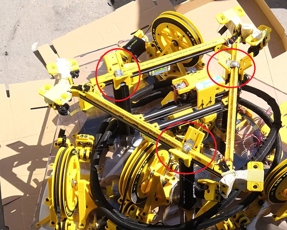
- mount complete line system at the ceiling module including the 6 bottom anchors. This reduces installation complexity a lot because you do not need to to the fuzzy work above your shoulders.
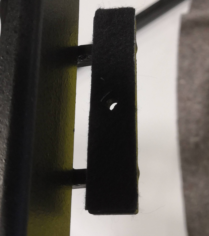
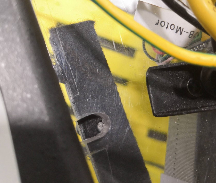
- While mounting the anchors ensure that all lines are put correctly in the ceramic inlets and bearing slots
- Ensure correct placement of the felted parts which prevent the lines to fall off from the lines but also check out if the bearings still can move smoothy. If the bearings cannot rotate properly the friction will get much higher which is bad for the movement system
Handling
The ceiling module has 2 handles on the top side and two handles on the bottom side. Additionally it has 3 ring bolts for other purpose fixation. While transportation ensure that the effector looks to the sky because it's not constructed to withstand 16 kg of weight.
Build steps for Trikarus
General
- Find the required tools and all necessary individual parts carefully before assembling! Better to pack too much than not enough!
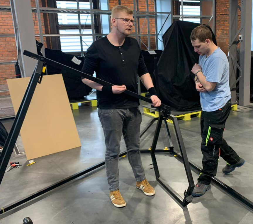
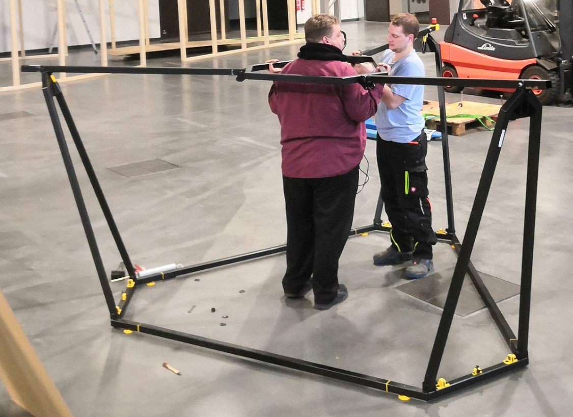
- At least 3 people are required to set it up. It has been proven that there is a great danger that the frame will tip over or that the helping hands will not be enough to hand over individual parts.
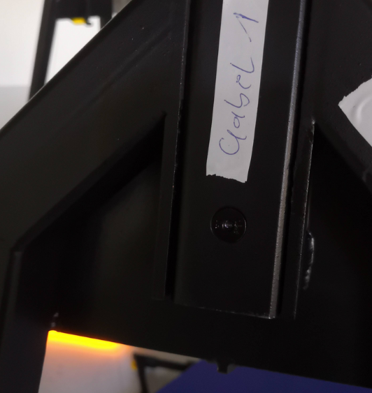
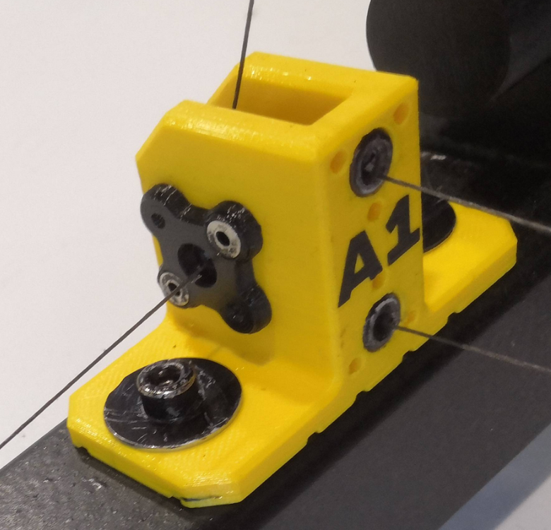
- Please check out all the frame parts. They are labeled with "A", "A1", "A2", "B", "B1", "B2", "C", "C1", "C2" to mark which frame part joins the other part. This is important for tolerances and for things like wiring of power management, network cables, USB webcam and PTFE tubing. They also mark the positions of the anchors/coordinate system that way.
I. Assembly steps: frame with ceiling module
Before assembling the frame, it should be ensured that all tolerances have been manufactured so that no moving parts seize. In our case there were tolerance problems, so that some parts had to be easily machined with a rubber hammer and the prepared nylon sliding washers could not be inserted at all points.
Before the frame is assembled, all individual assemblies must also have been prepared accordingly (pre-assembly).
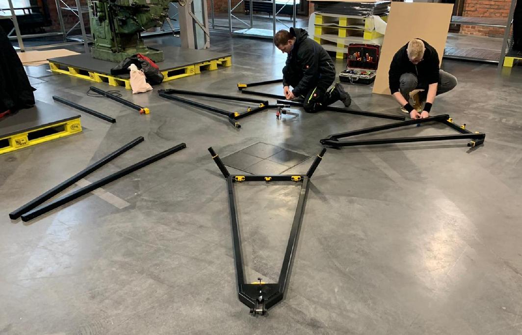
Spread parts on the floor
Spread out according to the rough arrangement on a flat place with sufficient free area around it (10 m² would be good!)
(Re)grease stainless steel bushes / fitting screws
So that the dowel screw connections (swivel joints) do not squeak, do not rust and go easier, they should all be lubricated. Use a grease gun to distribute some grease in the stainless steel bushings or on the fitting bolts. If necessary, spread with a brush.
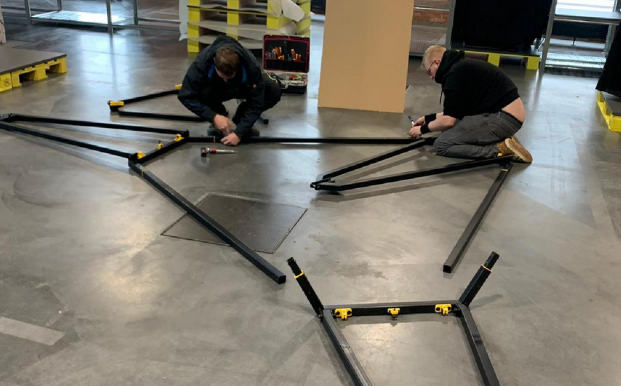
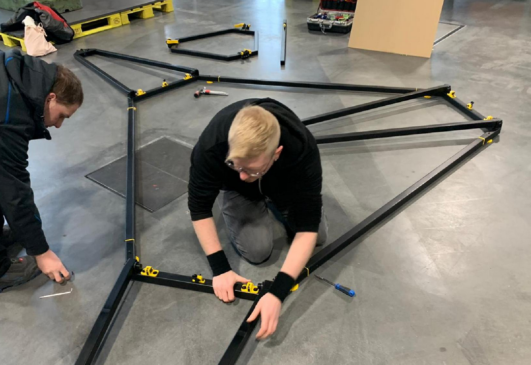
Join the hexagon
- First of all, the large hexagon is put together from the three prepared fork bases and the three belonging straight connector (fork top) profiles
- After that, all profiles must first be aligned with each other
- Then profiles can be screwed together (countersunk screws ISO 10642 M3 x 16 mm
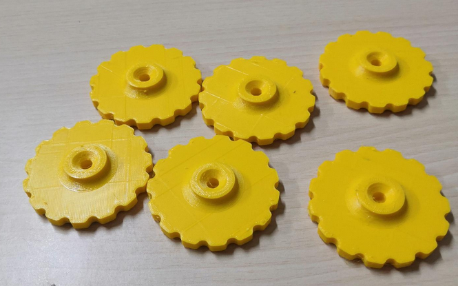
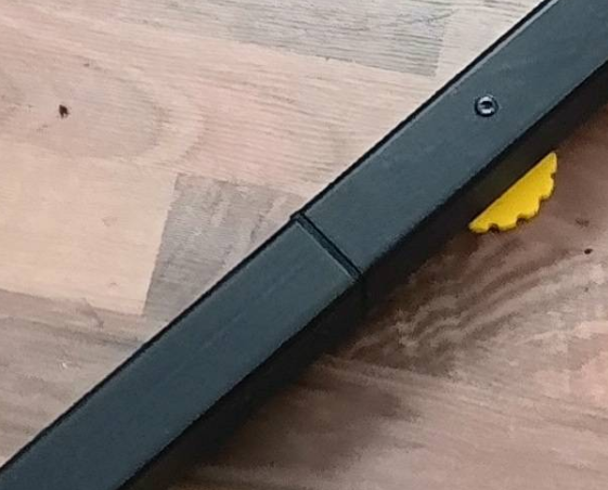
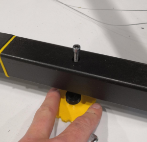
Place the feet under the frame
Place 6x frame feet under the frame and screw in the 6x socket head screws ISO 4762 clockwise until the cylinder heads are at least smooth / flush with the 40 mm steel profile. Do not screw them down yet. Please also double check that you use screws which have thread from bottom to top (full thread screws). The feet shall have no configured distance to the beams yet. They are getting adjusted after building and placing the frame assembly. They are used to adjust the levelness of the ceiling module later. The feet should be put under the frame before it get's heavy due to installation of all the required components. Remember that the whole printer weighs several kilograms. The assembled frame can be lifted by one or two persons if you want to put the feet under it later but that's not really recommended. If you need more distance you can use the provided spacers.
Move the frame to it's final target position
Please think of the place where Trikarus will stand. It needs stable ground. The flatter the better.
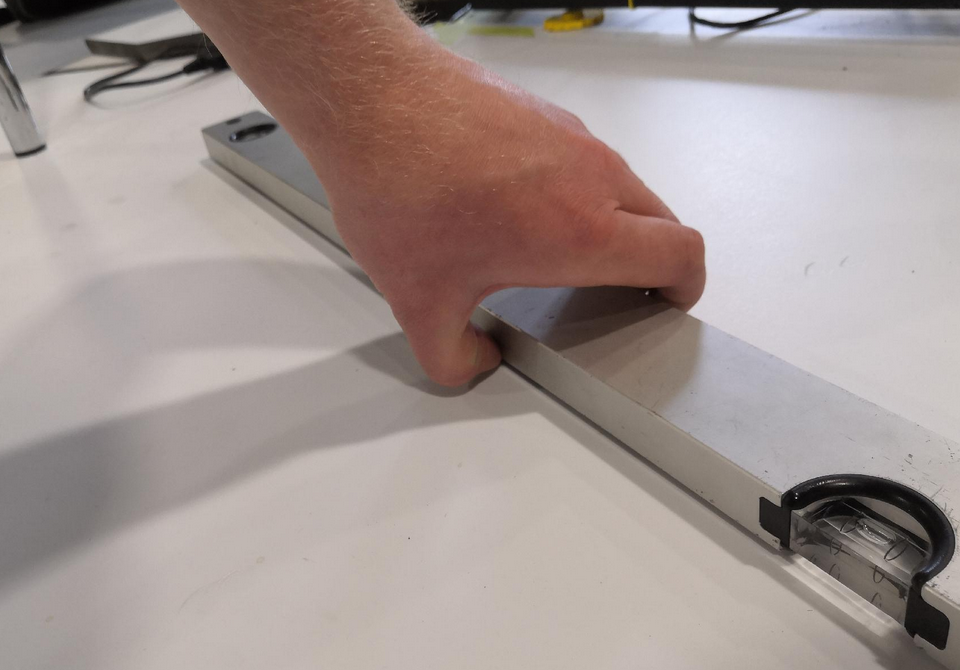
Please take a spirit level to check the levelness of your ground. You can also let roll a small ball or marble over the floor (maybe the marble does not roll because your ground is too soft or it's just really even). Then you have a first view where you will need to adjust your frame feet screws later. At the exhibition place where Trikarus was first installed the ground is not even. It has a small deviation.
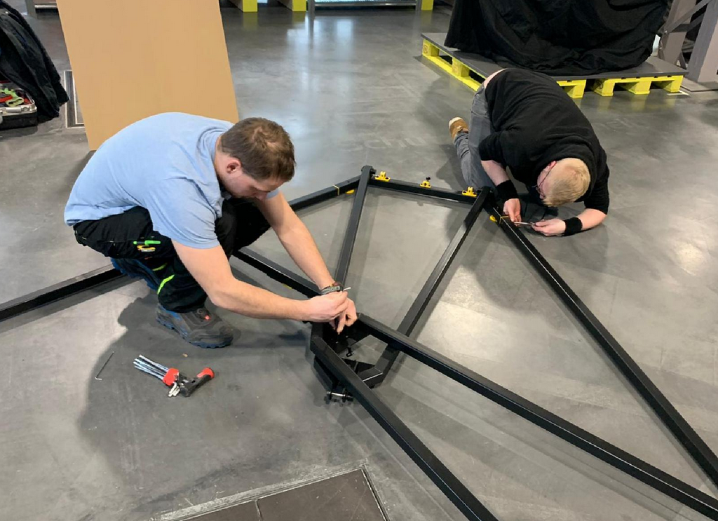
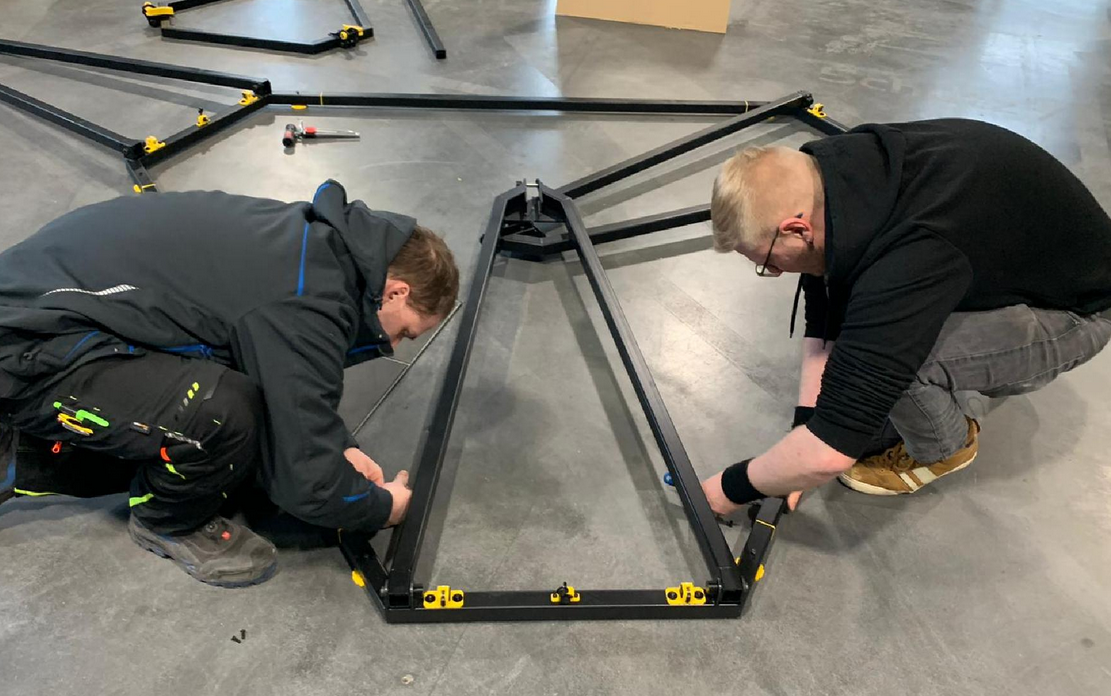
Screw on the fork top profiles
Screw on the 3 upper fork parts (straight profiles) and fold each into the inside of the frame as shown.
Required for each join:
- 2x huge washer made of TPE
- 1x fitting screw
- 1x disc spring
- 1x lock nut
- 1x lock nut cap made of PETG
If the fitting bolts seize, they can be easily hammered in with a rubber hammer. Normally they thread correctly through the stainless steel cylinder then.
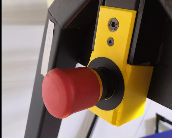
Since the frame is symmetrical, it doesn't matter where the emergency stop switch is attached!
Mount gas pressure springs
The 3 gas springs help to move the head plate module vertically more easily
Required for each join fork:
- 2x washer made of PE
- 1x collar screw
- 1x lock nut
- 1x lock nut cap made of PETG
The fork joints can then be folded back to the starting position (as in the previous step)
Hook in the upper part of the frame (upper hexagon) and screw together
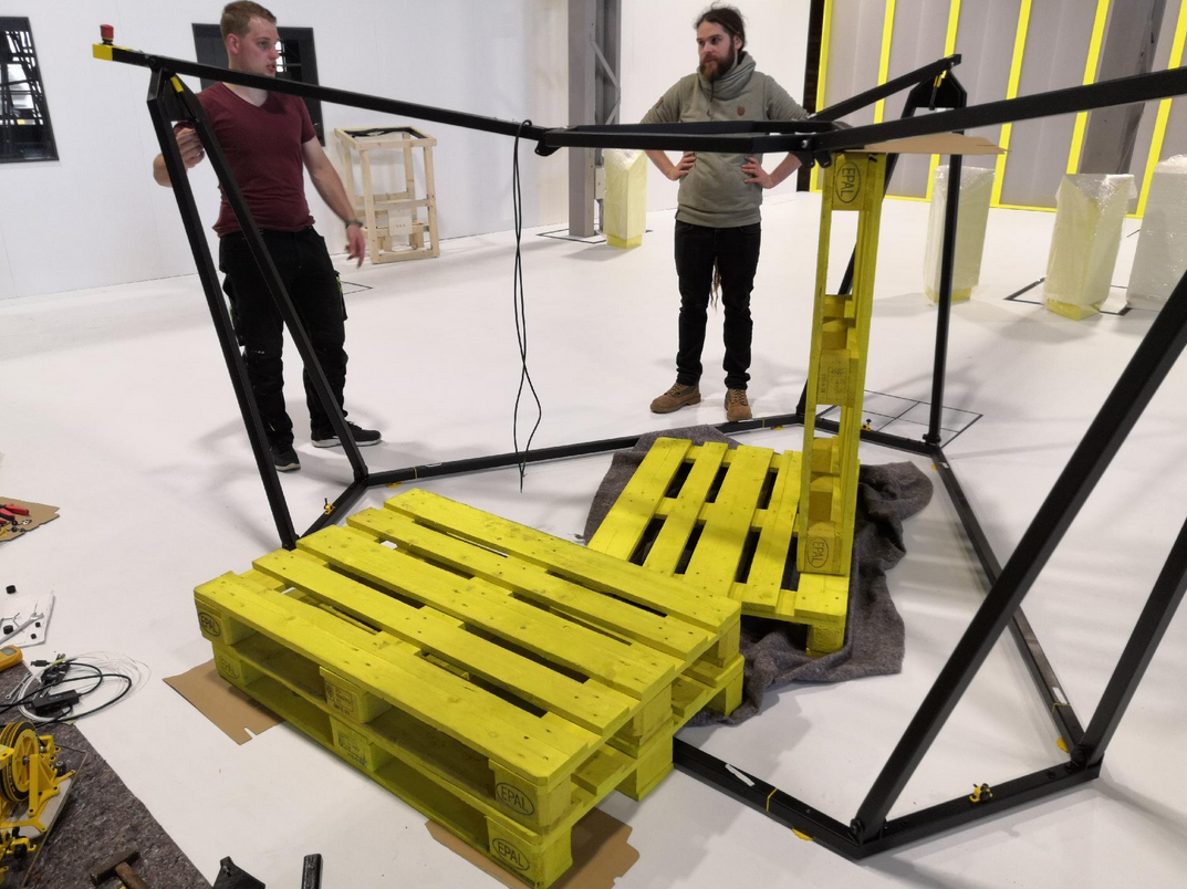
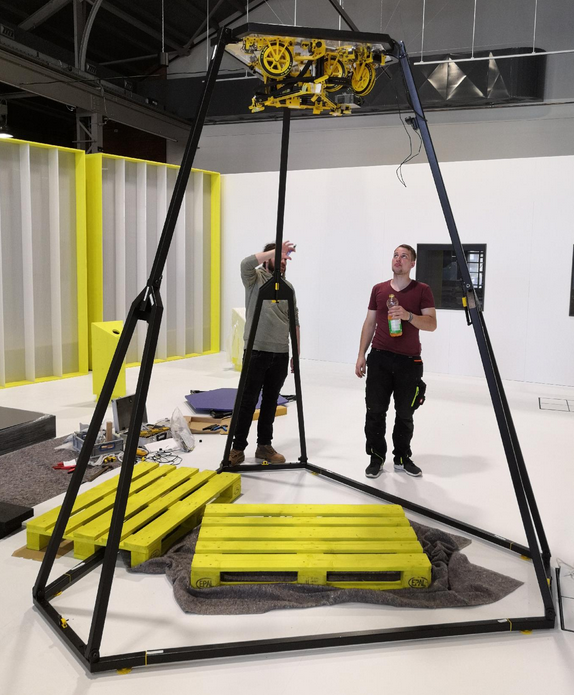
This step requires at least 3 people. 2 people have to hold the upper heaxgon while the third person makes the screw connections. Another cheat will be to put europallets below the hexagon. The first connection can still be made by two people (one person is holding, one person is screwing)
For each fork required:
- 2x huge washer made of TPE
- 1x fitting screw
- 1x disc spring
- 1x lock nut
- 1x lock nut cap made of PETG
If the fitting bolts seize, they can be easily hammered in with a rubber hammer. Normally they thread correctly through the stainless steel cylinder then.
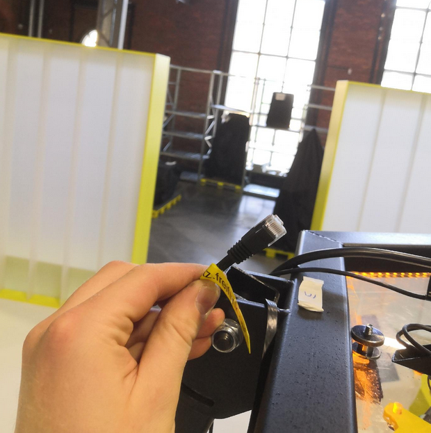
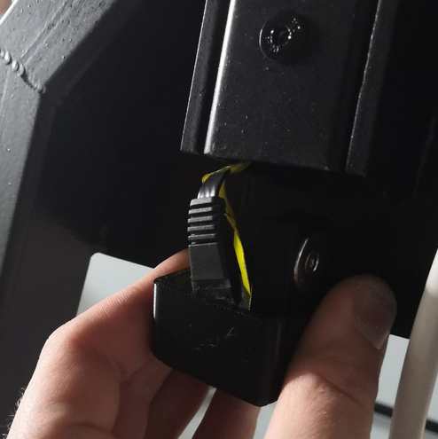
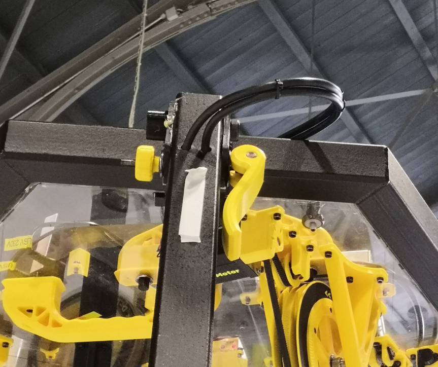
Put the LAN cable into one of the forks (except the fork with the emergency halt button)
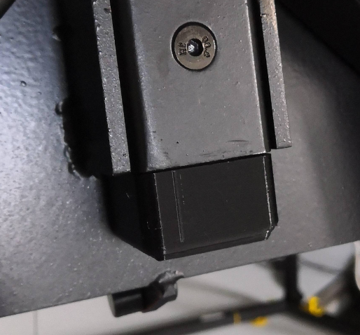
To have a local LAN access in case Wifi fails you have a wired fallback connection which can be hidden completely in the fork. Put the cable inside the beam and connect it to the router. Please use only flat style LAN cable because the frame will cut thicker cords (only rare space between top hexagon and fork pivot). Use the magnetic beam end cap to hide the cable if not used.
The photo shows Trikarus in an already installed state so please do not wonder!
Wire up the USB Webcam
Avoid climbing up to the roof by connecting the USB webcam before lifting the ceiling module to the maximum frame height.
Mounting and fixating the ceiling module
At first please install the felts between the top hexagon feets and the polycarbonate plate. This avoids scratching your material.
You cannot insert the module from downside. The ceiling module has to be inserted from the top side. Use the two handles on the top side to lay in. Insert the ceiling module so that the power supply has the shortest distance to the fork with the emergency halt cable.
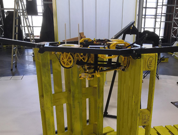
The photo shows a state where Europallets where put below the top hexagon. Reason for this are some instabilties with our current frame construction (gas springs lost huge amount of their gas)
Wiring the emergency stop button
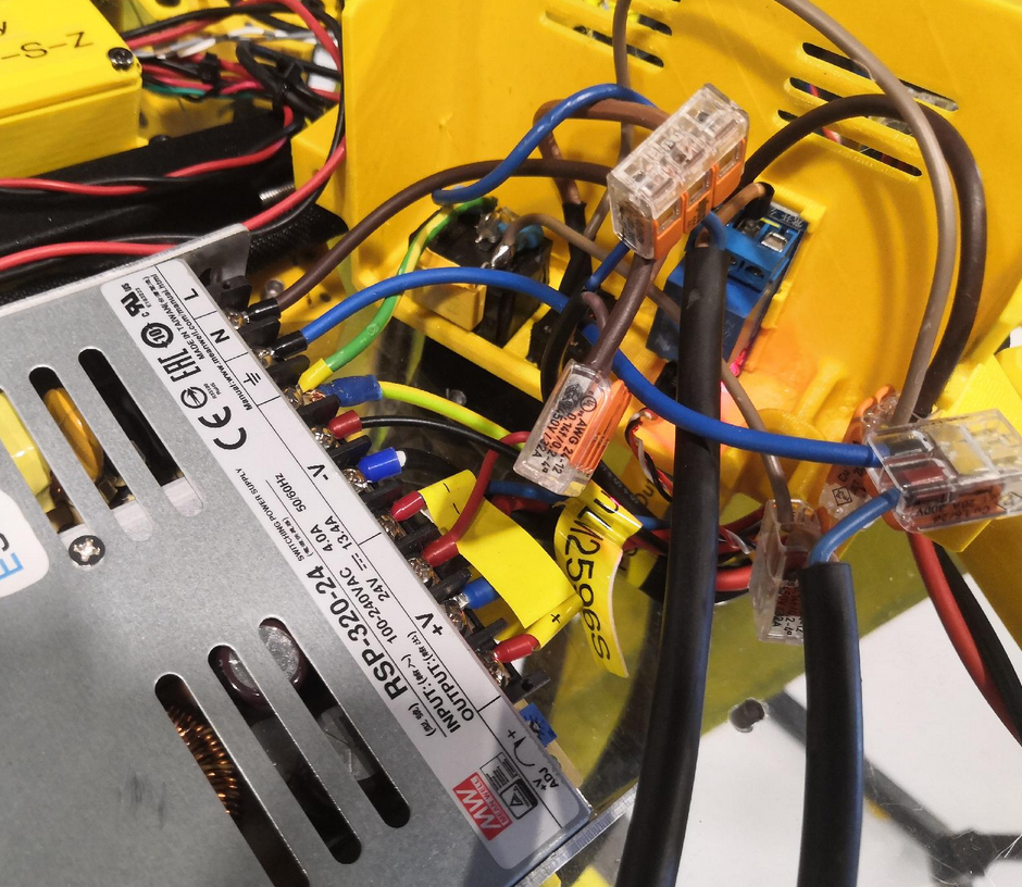
After installing the frame with head plate, the electrical connection between the emergency stop switch and the power supply must be created. There are two cable openings provided on the housing of the power supply. These still have to be wired.
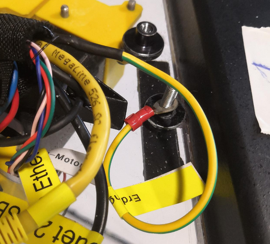
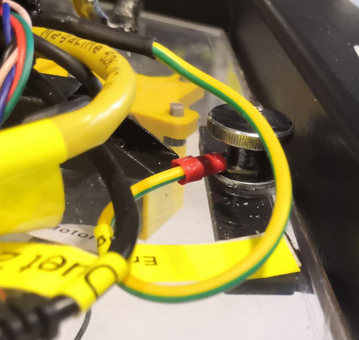
Wiring up the ground wire
The following installation is not really professional yet but it does the job
Connect the power cord to the printer
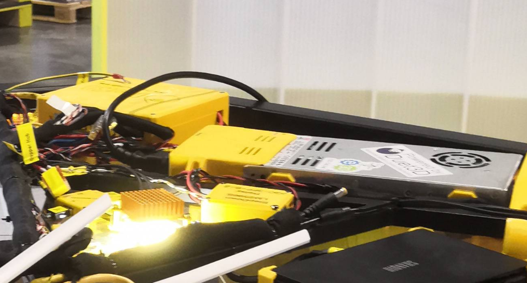
Connect the C14 power cord to the switching power supply, plug the other end into a socket and press the toggle switch. The internal relay should now have a red lighting LED and the power supply should turn on.
If your power socket (source power) is not on the ceiling, the electricity must be routed from the floor. To do this, the power cable must be laid on the machine frame.
Check all electronics before extending the printer to the top.
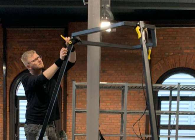
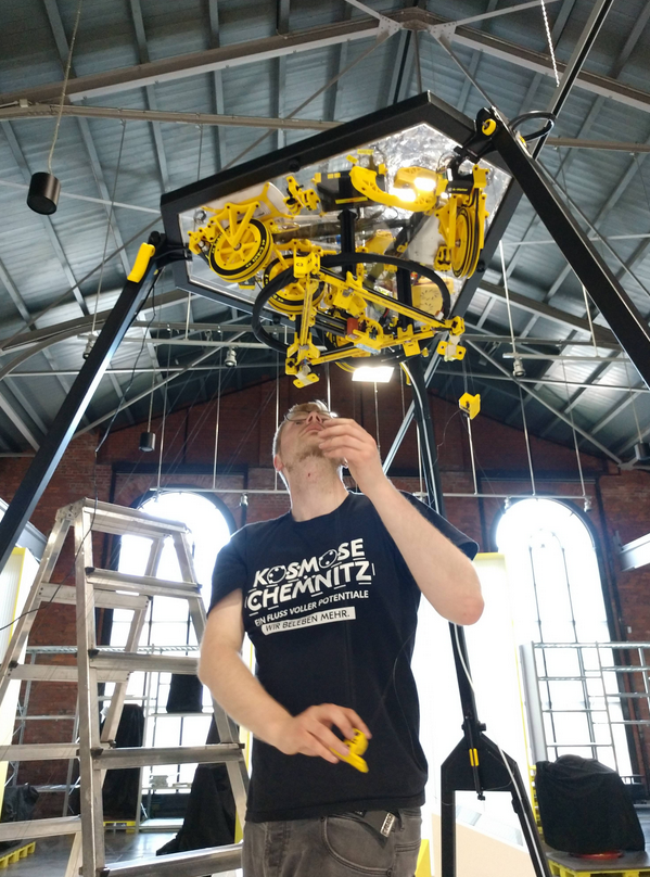
Extend the frame to the top
This step requires special attention.
- The frame must be extended slowly and with patience as evenly as possible
- Before moving out, it makes sense to place one person per fork corner. At each corner, some body weight should be shifted to the floor frame so that it receives additional support.
- Caution, risk of bending if the frame feet have already been unscrewed and you tap on the frame parts!
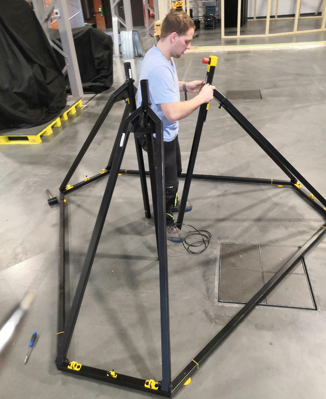
the left photo shows just some test
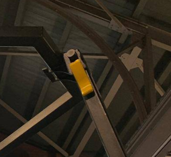
Fix the fork joints
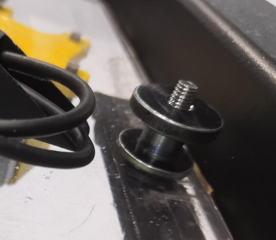
To fix the forks (prevents the folding movement), a countersunk screw ISO 10642 is screwed in for each fork.

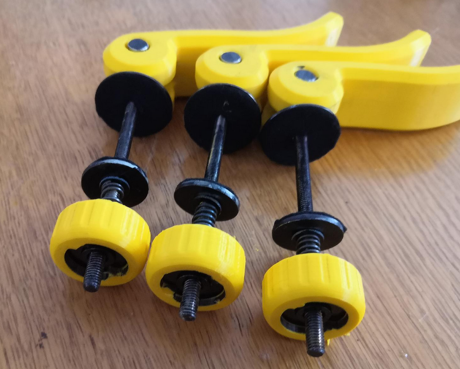
Attach quick releases
Install 3x quick releases and use them to stiffen the frame. These angle adjustments help to prevent the frame from tilting or wobbling due to different manufacturing tolerances a bit.
It may be necessary to open and move the quick releases several times. By leveling the frame, it is possible that the curvy elongated holes move slightly
Check frame stability
Check whether the frame wobbles very much. If yes: retighten all neccesarry screw connections (fitting screws) and check feet if they all touch the ground. There are 6 frame feet, 12 bolt connections, three quick releases and three fixation screws for the forks. All of them should have good contact. It's impossible to get the frame absolute non-wobbling. While running the printer this should not be the problem because no one ever should touch the frame or lines while printing. When shaking the frame it takes ~ 10 seconds until vibrations are gone.
Ceiling plate leveling
Before leveling the ceiling module you should check the general levelness of your ground (if not already done while placing the frame in the room). The fine leveling steps will be done later.
Take a spirit level and level the frame by configuring the height of the six adjustable yellow feet. You can put the level at the top surfaces of the three long connection beams between the fork corners. Adjust one feet per corner to adjust the frame like a triangle. The three remaining feet should hover due to missing contact with the ground now. If your frame is level you can adjust those remaining feet simply by screwing down until they get safe contact with the ground. Now the frame should be stable.
Ideally, the ceiling plate is now level too, provided the frame has been correctly leveled by adjusting feet and the frame tolerances are ideal. However, there is likely to be a discrepancy, even after having a level ground and a level frame. To check this we take another spirit level on the ceiling plate. Remaining angles can be corrected afterwards by placing a little felt between the ceiling module and the three welded support plates of the hexagon frame part or just by re-adjusting the feet screws on the frame bottom. You will also see (later) if your ceiling module is leveled well if your effector will sit in the three arms correctly at maximum Z because the installed Z endstop should trigger if everything is horizontal. If there is a gap between one or more arms and the effector, the ceiling plate is not level and/or the effector is not level too.
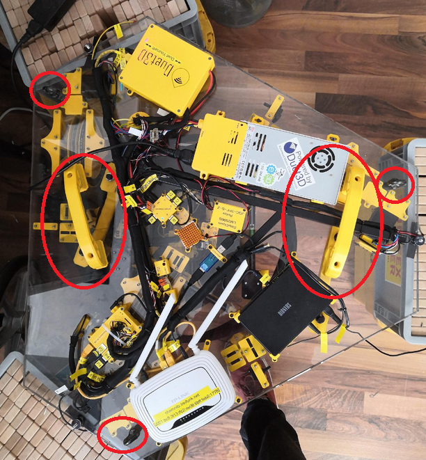
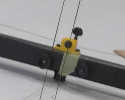
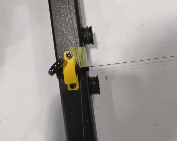
Mount the six bottom anchors
This step is only for installation purpose. The calibration is complex and will be done later.
- Pull down the lines from ABC drives to lower the anchors until you can screw them down to the frame corners. You will have to pull down A1/A2, B1/B2 and C1/C2 pair-wise. If you only pull one anchor (one line) than the other line of the spool will de-spool
- ensure that all felt fixators are installed properly without blocking the bearings. A smooth movement is required
-
check for collisions between ceramic inlets and the V bearings. Sometimes the inlets are pushed in too deeply into the base frame roller block. If thats the case push them into their correct fitting position again
- check all lines if there are any twistings between bottom anchors and effector. Each twist will lead to failing movement system
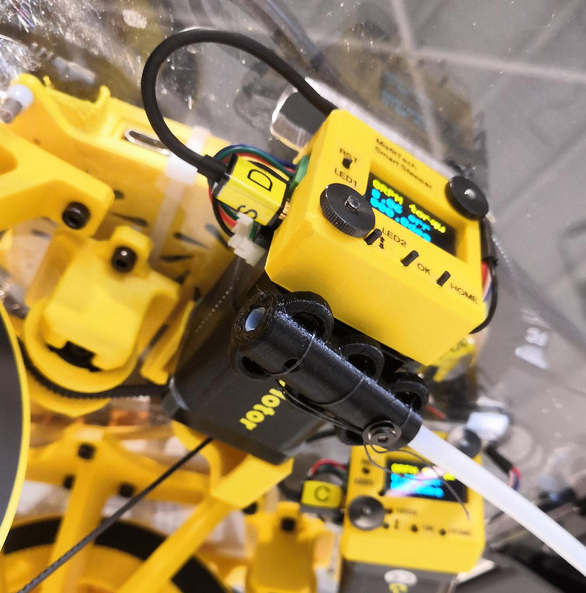
If there is power on the Smart Steppers and they are enabled they will not move when you try to pull the lines. To pull the lines you need to disable the Smart Steppers either by sending M84 command or by turning off the PSU power in the meantime. Another trick would be to push the reset button on the Smart Stepper LCD. Then you have around 5 seconds time to pull lines until it returns into previous control mode (sPID/pPID/torque).
Add filament tubing and join together with magnetic wire fixations
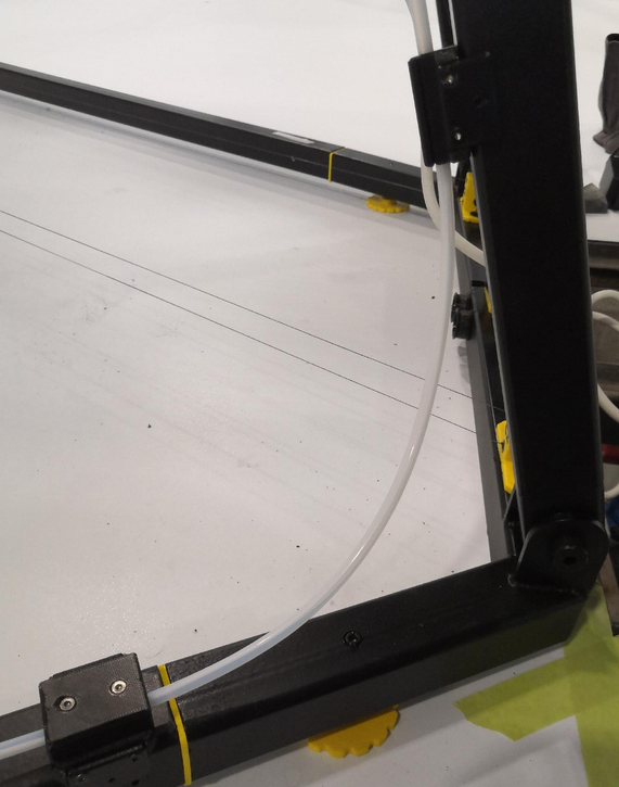
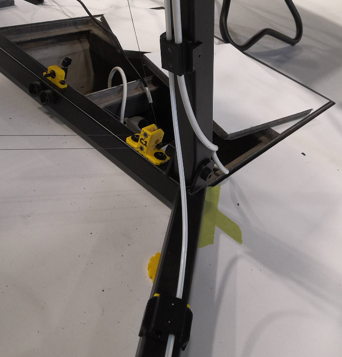
Mount the filament tube end piece
Take some fishing line and knot it below the D motor. The tubing should end at the same height level like the transport fixation arms.
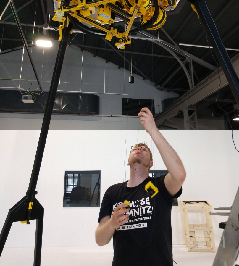
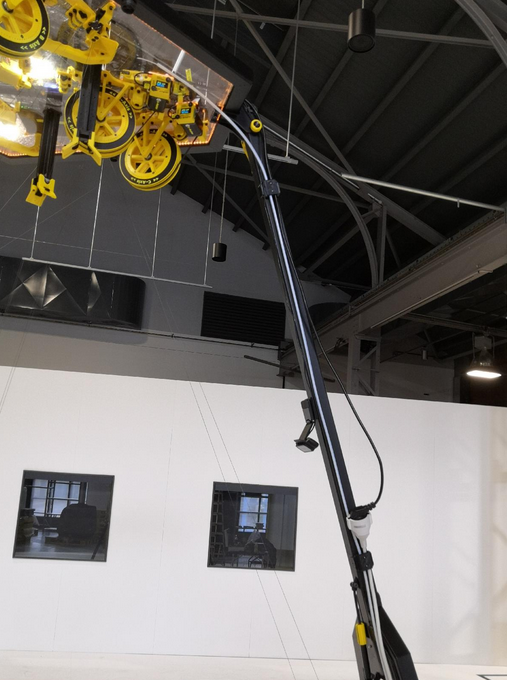
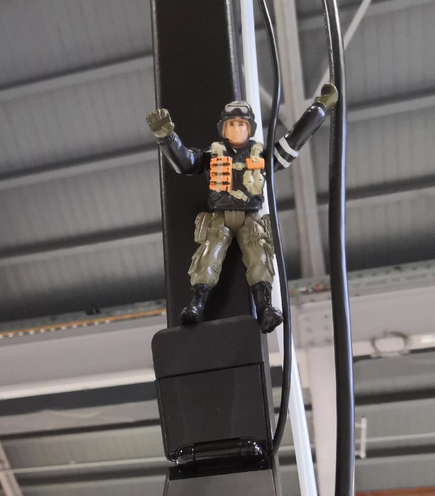
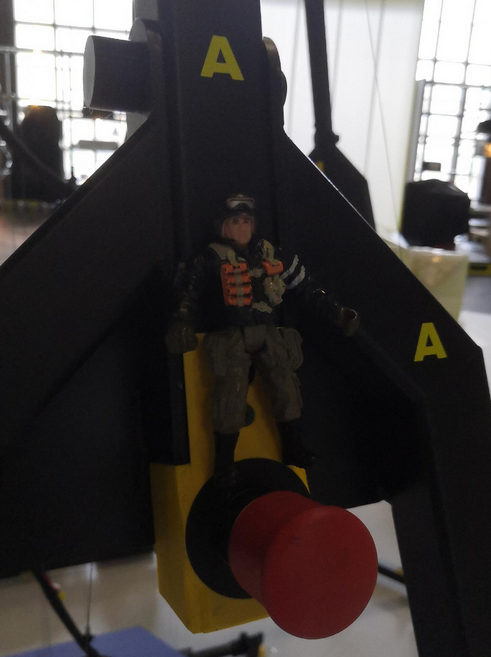
Let Smarty Mac Skydriver climb up to the top
He's a "magni"-tude guy and watches the emergency exit.
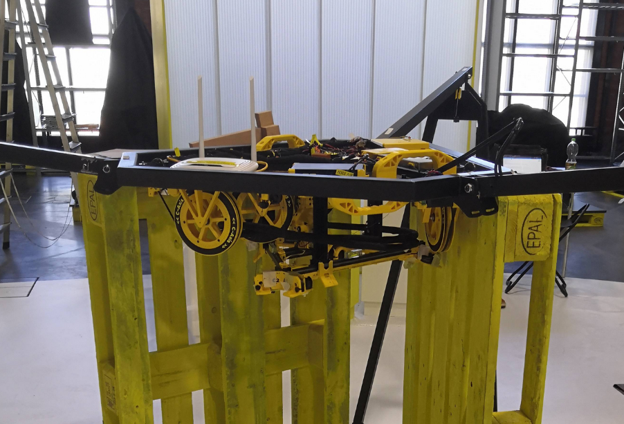
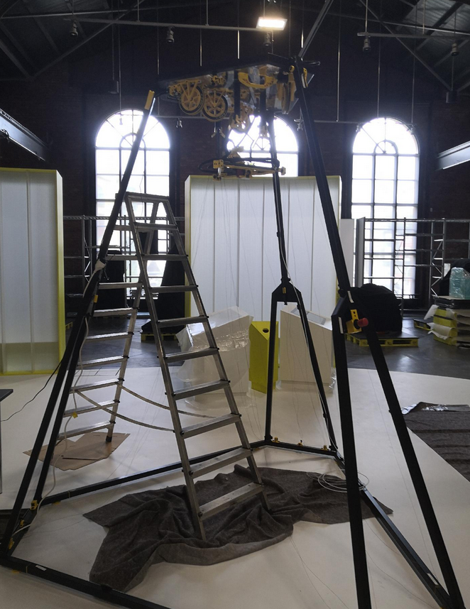
The base frame with ceiling module is fully assembled
To maintain the position, the frame corners on the floor can be additionally secured with markings using some tape. This step is particularly important if Trikarus would be installed in the room without the fixed frame.
Extra: sanity check of frame dimension
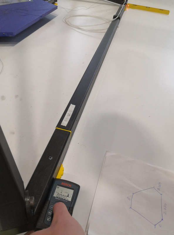
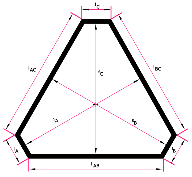
Do some sanity checks of the frame. This is optional because Hangprinters normally do not have a frame. But for better precision we try to measure all we can to find error sources quickly and in early states. In a Hangprinter without frame this is not relevant but for Trikarus exhibition frame we can use the benefits of this. The better the frame dimension are regular the easier it will be to adjust anchors later because the smaller the resulting angle deviations are. If the three verticals of the truncated triangle (hexagon style frame) are the same length this would be a perfect result. I remeasured all six frame bottom part lengths and the three distances between fork and the parallel connector beam on the opposite side, for each. So in total we get 9 measurements.
| Overview | Measurements of Trikarus frame |
 |
|
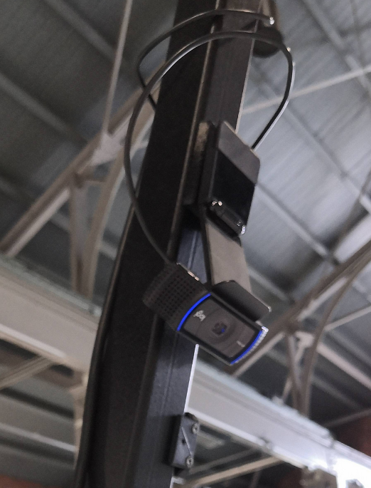
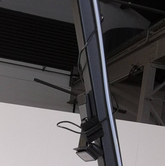
Adjust the webcam view to get a nice overview of the printer build volume
This image shows an already finished setup of Trikarus
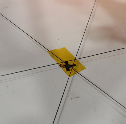
Mark the center of the frame
This step is a little bit dirty because we work on unknown ground (yet unknown grade of levelness)
We need the middle of the frame to (re)adjust the laser pointers for later usage. We use some magnetic line winders to create temporary helper lines between each anchor fork (take the center which is exacty below the guitar tuner) and it's parallel frame connector beam (take the half of it's length. That gives 800 mm).
Take some tape and put a marking on the ground.
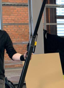
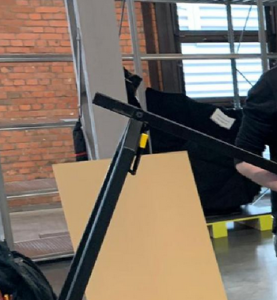
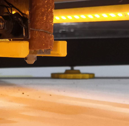
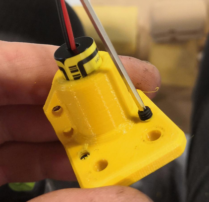
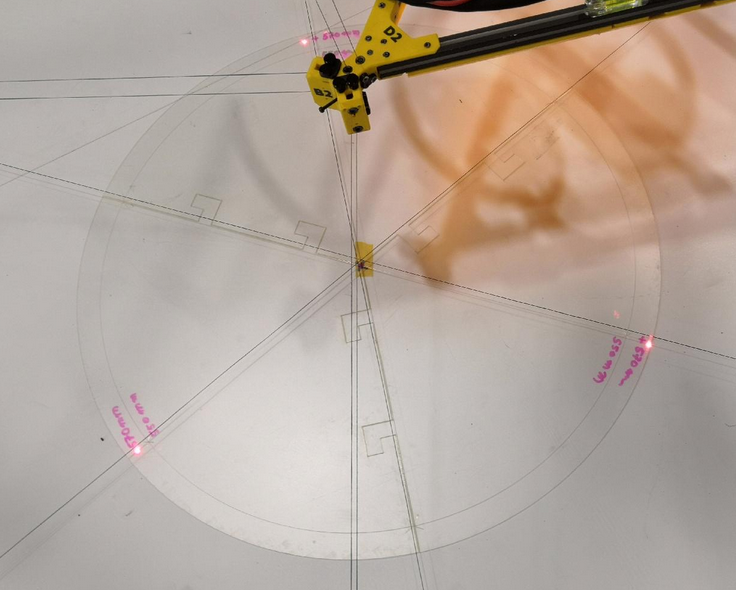
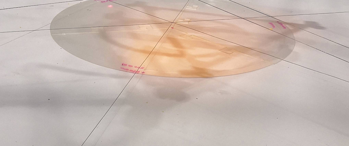
Adjust the laser pointers
To work out good calibration we make use of the three laser pointers at the ceiling module. But they are really sensible. We have to adjust their focus. To do this rotate the body of the laser pointers until the dot looks good. Additionally we need to adjust the position where the spots hit the ground. The angle of the pointers can be adjusted using the set screws. We make use of the template sheet with 570 mm circle and the three target markings. We use a 570 mm circle because the laser alignment has exactly the same size on the ceiling plate. Due to uknown ground levelness slight deviations may occure on the template (laser pointers could point slightly to different target position). Those can be fixed or reduced later.
II. Setup steps for the effector (mover)
|


III. Setup steps for printing platform
The print platform consists of 3 equal segment pieces which are small enough to be put into the back of a regular car (for transport). To keep it as simple as possible it has a form of an easy shape to produce with a plunge saw or cutting or milling machine. This is a lower cost but solid and plane solution. It's also not too heavy but heavy enough to keep in place. Other possible materials are regular wood, Multiplex, CDF, MDF, HPL-F, flagstone, glass, aluminum, circuit board, PET plate, PEI plate or Firepanel. Ideally you choose a material with low flammability.
|


IV. Configuring the movement system and final adjustments
|
||||||||||||||||


V. Setup steps filament feeder
![]() The planned filament feeder is not ready yet so use ordinary spool mechanism (spool on two free rotatable rods)
The planned filament feeder is not ready yet so use ordinary spool mechanism (spool on two free rotatable rods)
|

VI. Check the electronics
|
VII. Disassembly or emergency maintenance of the base frame (folding / dismantling)
|
