RepRapFirmware and calculations
Trikarus prerequisites: maths and calculations
Configuring the firmware requires a lot of mechanical / math values. So the following table provides calculations for various values needed to build up Trikarus.
| Meaning | Formula / results | Notes |
| pitch circle diameter pulley 20Z | $d_1 = \frac{t \cdot z_1}{\pi}= \frac{2 mm \cdot 20}{3.1415} = 12.732 mm$ | Pitch for 2GT is 2 mm |
| pitch circle diameter per spool ABCD |
$d_2 = \frac{t \cdot z_2}{\pi}= \frac{2 mm \cdot 255}{3.1415} = 162.338 mm$ |
Pitch for 2GT is 2 mm |
| coil radius per ABCD spool |
$r_{coil} = \frac{130mm}{2}= 65.000 mm$ |
Theoretical value. For a more precise line buildup compensation, the value should be measured exactly for each drive. Important hint: If you put your effector in origin and there is a lot of idling line on spools then you have to adjust the spool radii with the extra diameter which comes from the extra line because your "base diameter" is just larger than the printed plastic under the line. Each digit afer comma matters. |
| pitch circumference of pulleys |
$u_1 = d_1 \cdot \pi = 12.732 mm \cdot 3.1415 = 40 mm$ |
|
| pitch circumference of spools |
$u_2 = d_2 \cdot \pi = 162.338 mm \cdot 3.1415 = 510 mm$ |
|
| coil circumference of spools |
$u_{coil} = 2 \cdot r_{coil} \cdot \pi = 2 \cdot 65 mm \cdot 3.1415 = 408.407 mm$ |
One full round of huge spool wheel will move that amount of line |
| max. power Stepper Motors MT-1705HS200AE by Motech Motors |
$P_{max} = I_{max} \cdot U = 2 A \cdot 24 V = 48 W$ |
|
| transmission Stepper Motors MT-1705HS200AE by Motech Motors with 2GT pulley |
$i_1 = \frac{z_2}{z_1} = \frac{255}{20} = 12.754$ |
|
| steps Stepper Motors MT-1705HS200AE by Motech Motors |
$steps_{sm} = \frac {360}{stepper_{angle_sm}} = \frac {360}{1.8} = 200$ |
|
| microsteps Stepper Motors MT-1705HS200AE by Motech Motors |
$microsteps_{sm} = \frac {steps_{sm}}{steppingmode_{sm}} = \frac {200}{1/16} = 3200$ |
The steppers are configured to run at 1/16 microstepping mode. You can configure this setting at the Smart Stepper OLED Display or by setting it over USB serial. Any configured values in config.g of Duet won't work because they only control the TMC2660 onboard chips |
| max. number of revolutions for Stepper Motors MT-1705HS200AE by Motech Motors (theoretical) |
$n_1 = \frac{U}{2 \cdot L \cdot I_{max} \cdot steps_{sm}} = \frac{24 V}{2 \cdot 3.3 mH \cdot 2 A \cdot 200} = 545.455 RPM$ |
|
| max. number of revolutions for Stepper Motors MT-1705HS200AE by Motech Motors (measured) |
$n_1 = 650 RPM$ |
|
| max. number of revolutions at the spools ABCD (practically) |
$n_2 = \frac{n_1}{i_1} = \frac{650 RPM}{12,75} = 51 RPM$ |
|
| max. peripheral speed at the spools ABCD |
$v_1 = u_1 \cdot n_1 \cdot \pi = 510 mm \cdot 51 RPM \cdot 3.1415 = 81710.415 mm/min = 81.71 m/min = 1361.84 mm/s$ |
|
| max. rotations per minute at the spools ABCD (theoretical) |
$n_2 = \frac{n_1}{i_1} = \frac{545.455 RPM }{12.75} = 42.781 RPM$ |
|
| transmission of extruder gear Aero Titan Extruder and SuperVolcano Hotend by E3D |
$i_2 = \frac{z_4}{z_3} = \frac{66}{22} = 3$ |
22 teeth at the metal gear, 66 teeth at the black plastic gear |
| steps Stepper Motor MT-1703HSM168RE by Motech Motors |
$steps_{ex} = \frac {360}{steppingangle_{ex}} = \frac {360}{0.9} = 400$ |
|
| Extruder micro steps |
$d_{bed} = 2 \cdot \frac{1}{3} \cdot l_{ABC0} = 2 \cdot \frac{1}{3} \cdot \frac{2754.29}{2} = 918.1 mm$ |
https://e3d-online.dozuki.com/Guide/Titan+Aero+Marlin+Configuration/39 |
| max. recommended build diameter at z = 0 |
$f_{lbc} = \frac{(\frac{d_{line}}{2}) \cdot (\frac{d_{line}}{2}) \cdot \pi }{b_{coil} \cdot \pi} = \frac{(\frac{d_{line}}{2}) \cdot (\frac{d_{line}}{2})}{b_{coil}} = \frac{(\frac{0.5 mm}{2}) \cdot (\frac{0.5 mm}{2})}{7.5 mm} = 0.0083333 mm$ |
The build diameter (for slicing) is limited to the boundary inside the hyperbolic triangle which is created between the maximum effector travel distance points from the three anchor location directions.
|
| line buildup compensation factor |
|
|
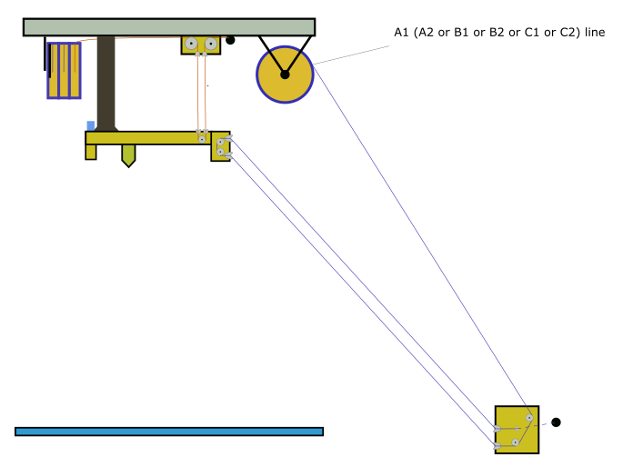
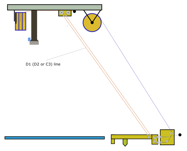
Required line lengths per spool and total line
We need enough line on each spool / coil to reach all desired coordinates within the build volume. If the physical lines are not long enough you cannot reach all the points you want to. Do not put less amount of line on the spools. You can put a lot more on the spool. All unrequired line, which has bad influence on calibration, can be wind up on the magnetic line winders (idle line catchers).
However, the minimum required line length of A, B and C can be calculated when the effector is at the highest reachable Z coordinate while the minimum D length can be calculated when the effector is at Z = 0 and parked at one of the outermost anchor points (A or B or C). If your build volume is not regular use the anchor point with the largest distance. The required line depends on the fact if you are using single or doubled lines and how big the distances between the ABCD points are and what other distances have to be bridged (knots, deflection bearings, ...).The required line length can be calculated using some easy formulas with rough ABCD anchor coordinates or just height and diameter. If you are planning to install a Hangprinter in your living room just make some quick measurements using some ruler or laser distance meter and draw a tetrahedron on a piece of paper containing coordinates. A coordinate system with ABCD scheme can be found at Building basics, checks, maintenance.
Trikarus is configured using the line "M669 A0.0:-1166.00:-21.13 B1010.00:585.00:-25.26 C-1015.00:578.00:-28.55 D2617.33 ;coordinates of anchor points". Rough dimensions of frame are 2.8 m in height and 2.25 m in diagonal direction. We used double lines so we need a lot more line. We do some quick calculation using height and diameter:
$l _ {ABC}= \sqrt {h^2 + (\frac{d}{2})^2} \cdot 3 + spoolbuffer_{ABC} + extra_{ABC}= \sqrt {2800 mm ^2 + (\frac{2250mm}{2})^2} \cdot 3 + 2000 mm + 1000 mm \approx 12053 mm$
$l _D= \sqrt {h^2 + (\frac{d}{2})^2} \cdot 2+ spoolbuffer_D +extra_D = \sqrt {2800 mm ^2 + (\frac{2250mm}{2})^2} \cdot 2 + 2000 mm + 1000 mm \approx 9035 mm$
For Trikarus we put $\frac{l_{ABC}}{u_2} = \frac{12053 mm}{408.407 mm} \approx 30$ windings for each ABC line and $\frac{l_{D}}{u_2} = \frac{9035 mm}{408.407 mm} \approx 22$ windings for D lines each. So in total we need $l_{total} = 3 \cdot 9035 mm + 6 \cdot 12053 mm \approx 99.5 m$ of line.
Notes about RepRapFirmware choice
Why to use Torbjørn's fork of RRF?
-
Trikarus uses line buildup compensation which is not part of official firmware
- Trikarus uses doubled lines feature which is also not part of official firmware
Why not to use Torbjørn's fork of RRF?
- unmaintained → a lot of nasty bugs are already fix in newer releases of official RRF
- Trikarus does not use I2C and ODrive BLDC motor things, so some of the GCode implementations are not useable (like G95 torque mode, G96, M114 S1, M569). Have a look at https://vitana.se/opr3d/tbear
Trikarus RepRap Firmware Configuration
- used RepRap Firmware (Fork):
- Version: "RepRapFirmware for Duet 2 WiFi/Ethernet 2.02(RTOS) (2018-12-24b1)"
- File: https://gitlab.com/tobben/hangprinter/-/blob/version_4_dev/firmware/RepRapFirmware/Duet2CombinedFirmware.bin
- Commit ID
- on github: https://github.com/tobbelobb/RepRapFirmware/commit/2490d5063f41ea09190661129d66be5eddd7c4e0 from 07/04/2019
- on gitlab: https://gitlab.com/tobben/hangprinter/-/commit/f4022e7cd720576a73f7e650658062dfbb4f2b93 from 07/04/2019
-
this compiled firmware .bin is maybe one commit behind the latest hangprinter commit: https://github.com/tobbelobb/RepRapFirmware/commit/2490d5063f41ea09190661129d66be5eddd7c4e0
-
the source code is kept on github, but the release is on gitlab (because Torbjørn moved the development from one platform to another)
- used Duet Web Control Version: DuetWebControl-1.22.6.zip (https://github.com/dc42/RepRapFirmware/releases/tag/2.02 - fitting toTorbjørn's RRF fork)
config.g (based on https://gitlab.com/tobben/hangprinter/-/blob/version_4_dev/firmware/RepRapFirmware/config.g
The values on this config are based on ...
- recommandations from vendors' products. Please check the datasheets
- max. hotend temperature (with SuperVolcano silicon sock / without silicon sock)
- stepper driver speeds and torques
- own knowledge
- forum postings
- a lot of experiments and failures
The configuration of RepRapFirmware can be easily done using Duet Web Control (integrated editor) or by using the command M997 ("perform in-application firmware update").
; config source: https://gitlab.com/tobben/hangprinter/-/blob/version_4_dev/firmware/RepRapFirmware/config.g
; Communication and Network
M540 P0xXX:0xXX:0xXX:0xXX:0xXX:0xXX       ; MAC Address
M111 S0                                   ; Debug off
M550 PTHEDEVICENAME                       ; Device name on the network
M551 PTHEPASSWORD                         ; Machine password (used for FTP)
;M552 S1 P0.0.0.0                         ; Turn network on (DHCP)
M552 S1 PXXX.XXX.XXX.XXX                  ; Turn network on and set static IP address (switch mode)
;M586 P2 S1 T0                            ; Enable Telnet (for Repetier Server Ethernet Connection) - this is disabled again due to security issues in public ffcmesh (Freifunk)

; GCode Flavour
M555 P2                                   ; Set output to look like Marlin
G21                                       ; Work in millimetres
M83                                       ; relative extruder moves

; Drives - directions (clockwise / counter-clockwise) and other core parameters
; see also https://duet3d.dozuki.com/Wiki/Choosing_and_connecting_stepper_motors
; see also https://duet3d.dozuki.com/Wiki/Using_external_stepper_motor_drivers
M669 K6                                   ; This is a Hangprinter - enables ABCD-parameters in gcodes that refer to motors
M569 P0 S1  R-1                           ; Drive 0 goes forwards - disabled
M569 P1 S1 -R1                            ; Drive 1 goes forwards - disabled due to destroyed chip :-(
M569 P2 S1 -R1                            ; Drive 2 goes forwards - disabled
M569 P3 S0                                ; Drive 3 goes backwards - used for extruder E0
M569 P4 S1 -R1                            ; Drive 4 goes forwards - disabled
M569 P5 S1 R1                             ; Drive 5 (A) winds up + enabled signal is set to active high (Smart Stepper)
M569 P6 S1 R1                             ; Drive 6 (B) winds up + enabled signal is set to active high (Smart Stepper)
M569 P7 S1 R1                             ; Drive 7 (C) winds up + enabled signal is set to active high (Smart Stepper)
M569 P8 S1 R1                             ; Drive 8 (D) winds up + enabled signal is set to active high (Smart Stepper)
M584 A5 B6 C7 D8 P4                       ; map ABCD-axes to ext driver pins (four visible)
M584 E3                                   ; Drive 3 (E0) has attached extruder motor

M669 P500.0                               ; Hangprinter printable radius (unused for now)
M669 S200                                 ; Hangprinter segments per second
M669 A0.0:-1166.00:-21.13 B1010.00:585.00:-25.26 C-1015.00:578.00:-28.55 D2617.33 ;coordinates of anchor points

M666 Q0.0083333                           ; buildup compensation factor for ABCD
M666 R64.965:64.965:64.965:64.975         ; ABCD radii
M666 U2:2:2:2                             ; Mechanical advantages on ABCD - 2 stands for doubled lines
M666 O1:1:1:1                             ; Number of lines per spool or "coil mode" (each line has it's own coil). 1 = coil style
M666 L20:20:20:20                         ; Motor gear teeth of ABCD axes
M666 H255:255:255:255                     ; Spool gear teeth of ABCD axes
M666 J200:200:200:200                     ; Full steps per ABCD motor revolution

; Drives - speeds, accelerations, step rates
M350 E16 I1                               ; Set 16x microstepping with interpolation for all extruders - XYZ microsteps are configured at Smart Stepper directly!
M92 E837                                  ; Set axis steps/mm for extruder. ABCD are configured by M666 parameters. Do NOT use M92 for ABCD because you might override buildup compensation values from M666 in that case
M201 X1000 Y1000 Z1000 E1000              ; Accelerations (mm/s^2)
M203 X9500 Y9500 Z9500 E3600              ; Maximum speeds (mm/min) - ABCD are configured by setting XYZ - there is !NO! M203 A<val> B<val> C<val> D<val> - The extruder's max. feed was tested by experiment. Higher feed values result in a non-moving extruder motor which gets hot.
M566 A900 B900 C900 D900 E1200            ; Maximum instant speed changes mm/minute
M906 E1400 I60                            ; Set Extruder drive motor currents (mA) and increase idle current to 60%; motor currents for Smart Stepper are set by bash script

; Endstops and axis limitations
M574 X0 Y0 S0                             ; set active low and disabled endstops for XY
;M574 Z2 S0                               ; set active low Z endstop
M574 Z0 S0                                ; OVERRIDE TEMPORARILY DISABLED
M208 S0 Z2000.00                          ; set maximum Z at D anchor
M208 S1 Z-10.0                            ; set minimum Z at D anchor

; Fans - note: "FAN1 is on by default at power up, for maximum safety when you configure it as a thermostatically-controlled fan."
M106 P2 S255 I0      H-1    C"Laser Pointers"  ; set fan 2 value and normal PWM signal. Thermostatic control is turned off
M106 P1 S0   I0 F500 H0 T60 C"Hotend"          ; set fan 1 value, normal PWM signal and frequency. Thermostatic control is turned on
M106 P0 S0   I0 F500 H-1    C"Blower"          ; set fan 0 value, normal PWM signal and frequency. Thermostatic control is turned off

; Heaters and thermistors
M140 H-1                                  ; there is no heatbed so we remove it
M305 P0 X200 C"PT100"                     ; PT100 for heater 0 (which is normally the first hot end heater)
M143 H0 S275                              ; maximum heater temperature to 275°C to have a floor of +25°C to PID tuned temp. of hotend. PLEASE NOTE THE MAXIMUM OF 260°C for heater block silicone sock from E3D Super Volcano

; Extruder tool definitions
M570 S180                                 ; Hot end may be a little slow to heat up so allow it 180 seconds
M302 S150                                 ; Allow extrusion starting from 150°C (prevent cold extrusions)
M307 H0 A796.0 C471.1 D6.6 V24.2 S1.0 B1  ; Super Volcano 80W 24V - connected to bed heater - Auto PID Tuning for 250°C
M563 P0 D0 H0 F0 S"SuperVolcano"          ; define tool 0 (extruder) with fan 0 as print fan, heater 0, extruder E0
G10 P0 X0 Y0 Z0                           ; set tool 0 axis offsets
G10 P0 R0 S0                              ; set initial tool 0 active and standby temperatures to 0°C
M200 D1.75                                ; set all extruder filament diameters to 1.75mm - required for volumetric extrusion
M207 S0.8 R0.0 F2500 Z0.8                 ; configure firmware retraction to allow usage of G10/G11 commands by PrusaSlicer. S is retraction length, F is feedrate, Z is lift height

; Miscellaneous
M404 N1.75 D1.4                                    ; M404: Filament width and nozzle diameter - only used for the print monitor
M911 S22 R23 P"M913 X0 Y0 G91 M83 G1 Z3 E-5 F1000" ; set voltage thresholds and actions to run on power loss (22V shutdown, 23V resume)
T0                                                 ; select first tool
G28                                                ; set machine homed at the beginning - MAYBE A BAD IDEA
M912 P0 S-12.0                                     ; Duet MCU temperature correction - measured against hotend PT100 sensor while Duet was idling/USB powered only

; Infrared Z probe and compensation definition - https://miscsolutions.wordpress.com/mini-height-sensor-board/
M558 P1 H15 F800 T4000 ; set IR probe with 15 mm dive height, 800mm/min dive speed and 4000 mm/min feedrate to the probe point
G31 P500 Z0.0

; re-enable steppers after reboot / triggering Emergency STOP by moving shortest possible distance. because the Stepper Motor will be disabled which leads to self-lowering effector
; values lower than 0.01 do not work (0.001 has no effect). Better way would be to send just an enable signal. Unfortunately there is no G-Code for this.
G0 H2 A0.01
G0 H2 B0.01
G0 H2 C0.01
G0 H2 D0.01
G90  ; absolute coordinates
Notes about XYZ movements and spool drive rotation directions
There are multiple ways to configure the rotation direction of the stepper motors (e.g. physical wiring, soft pin configuration over Smart Stepper UART interface or display interface, RRF configuration). To make Hangprinter move correctly understand your coordinate system. Minimum Z is where nozzle touches the print platform and maximum Z points to the ceiling. Y+ shows into the opposite direction of the A anchor. X+ points to B anchor (with angle). To make any Hangprinter move to be successful in XYZ there just the easy rule: Do a simple Z+ move and check if D winds up while A, B and C de-spool some line. If you wired up all motor wires the same pattern by plugging all motors the same way on the motherboard, configured all motors to run in same direction in RepRap Firmware and Smart Stepper Firmware then you are ready (no need to invert any motor direction).
The used stepper motors (Stepper Motors MT-1705HS200AE by Motech Motors) have 1.8° step angle. This gives 200 steps per revolution. Using 1/16 micro stepping we get 200 * 16 = 3200 microsteps. So 3200 micro steos let the small 20 tooth pulley turn exactly one round. The Transmission is ratio 255:20 which gives . The coil circumference of the huge gear without line buildup compensation is basically 408.407 mm. So 40800 microsteps are 408.407 mm of movement.
Line buildup (or spool buildup) error and compensation
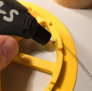
By spooling up and down the drives the lines are drifting on the spool from left to right. They lay over each other. So they generate some kind of random buildup and some random dancing from side to side (alternating movement). That means by each millimeter of line on spool the winding diameter gets larger which changes the pitch or the distance you need to (de)spool to reach a certain physical position. Because usual drive solutions have a constant pitch this does not matter. For Hangprinter it does. The following sketch tries to address the issue. Having a coil width of 7.5 mm and 0.50 mm line diameter you can put a maximum of $n_l = \frac{7.5mm}{0.5mm}=15$ rounds next to each other without buildup. The 16th line has to lay over existing line after one full round of spooling up. Having a base spool radius of 65 mm the circumference for one rotation $u = 2\cdot \pi \cdot 65 mm = 408,407mm$. Because we use doubled lines and our frame is ~ 2.5 meters high we need to spool up ~5.0 meters of line to reach the top (D drive). This gives $n_{rot} = \frac{5000mm}{408.407mm}=12.24$ rotations required (note that this calculation ignores the buildup itself). Finally with 12.24 rotations and 0.50 mm line width we get a theoretical minimum of $err_h = 12.24 \cdot 0.50 mm = 6.12 mm$ (if ignoring a perfect packing of the circles instead we imagine that they stack like cubic rectangles). In regular use the buildup is imperfect so the error can be higher. We exspect to have at least 0.5 to 2 cm of error we wish to compensate. Expressed in Z layers we would have a total shifting of 4 to 8 layers of 0.8 mm height each. The error problem is similar to ABC drives and even higher because ABC drives have to spool up more line amount than the D drive.
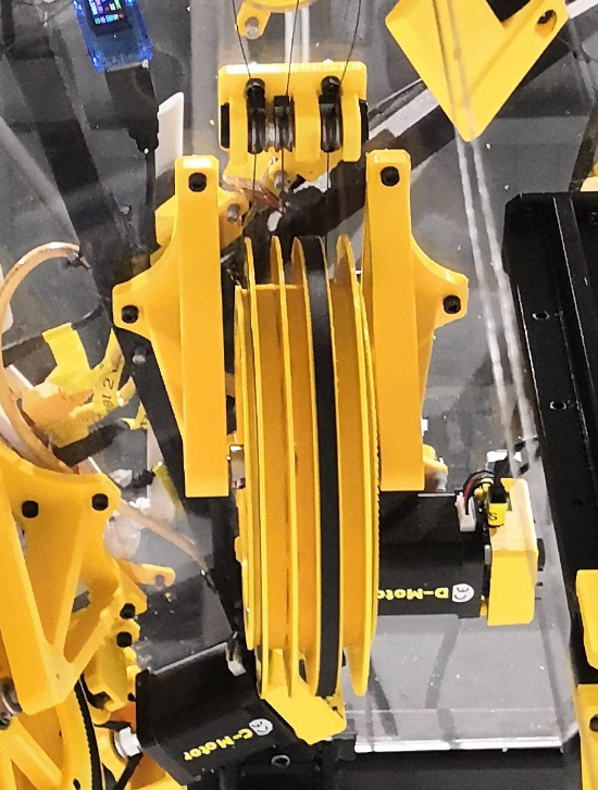
| Line buildup on a coil (spool) | base diameter with knot | fully spooled D drive |
|
|
|
|
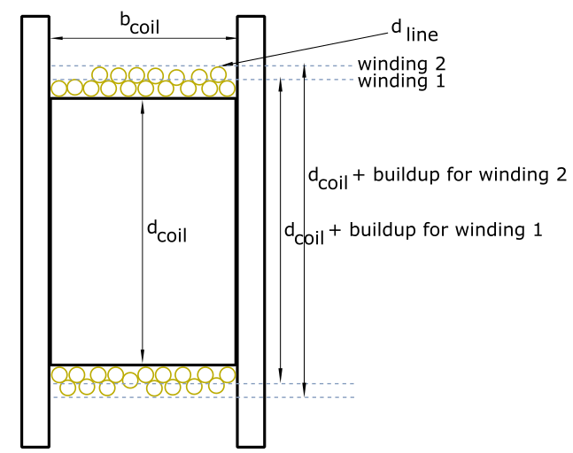
The base coil diameter is given by the manufactured part and is a constant. But the more line on coil the more buildup you have. A compensation factor can be calculated by known values like line diameter, coil width and coil diameter. Torbjørn implemented this feature in the past and put the algorithm into Marlin firmware and RepRap Firmware (at the moment this cannot be found in the official repository but in a fork). The line buildup compensation in RepRapFirmware is expressed by one Q value for all drives and four different R (radii) parameters - one for each drive. It will be configured using M666 command.
Notes about Smart Stepper wiring, enabling and timings
There's a thread on Duet forum which gives the tip to adjust the pulse width in case steps are lost: https://forum.duet3d.com/topic/7952/smart-stepper/4. This was not tested but may help in case of failures between Duet 2 and MisfitTech Smart Stepper. Regarding to GCode documentation the T parameter of M569 command says: "Taa:bb:cc:dd (firmware 1.21 and later) - Minimum driver step pulse width, step pulse interval, direction setup time and direction hold time, in microseconds".
M569 P5 S1 R1 T1:2:20:0  ; Drive 5 (A) winds up + enabled signal is set to active high (Smart Stepper)
M569 P6 S1 R1 T1:2:20:0  ; Drive 6 (B) winds up + enabled signal is set to active high (Smart Stepper)
M569 P7 S1 R1 T1:2:20:0  ; Drive 7 (C) winds up + enabled signal is set to active high (Smart Stepper)
M569 P8 S1 R1 T1:2:20:0  ; Drive 8 (D) winds up + enabled signal is set to active high (Smart Stepper)
The Smart Steppers get their enable signal from Duet signals. If you want to permanently enable Smart Stepper you canput a 1kOhm pullup resistor between VIN and EN terminal connectors on the Smart Stepper board terminal. This way Smart Steppers keeps enabled even after a reboot. But you can also wire them up the standard way and set R1 parameter of the M569 command. But in case M18 or M84 or board reset is done the motors get disabled. More details can be found at https://github.com/Misfittech/nano_stepper/issues/40. A workaround for the reset was made by including in config.g:
G0 H2 A0.01
G0 H2 B0.01
G0 H2 C0.01
G0 H2 D0.01
Notes to retraction
E3D give some tips regarding to the retraction values for Aero extruder (https://wiki.e3d-online.com/E3D-v6_Troubleshooting). They say "A common issue is massively excessive retraction distances. In direct configurations retraction of 0.5 to 2mm is all that should be needed for ooze-free prints. We use around 0.6mm for ABS that oozes very little, and 2mm for the very floppy flexible filaments that like to ooze a great deal and need a good tug to pull back the soft filament from the melt zone. For PLA we stick with retraction settings no higher than 0.8mm."
Hotend PID Tuning
Let's get good results with the mounted extruder. For this we can adjust some heating parameters in the firmare. Do the following:
; Run auto PID Tuning for Hotend
M303 H0 S250

;Get the calculated values
M307 H0

Heater 0 model: gain 796.0, time constant 471.1, dead time 6.6, max PWM 1.00, calibration voltage 24.2, mode PID, inverted no, frequency default
Computed PID parameters for setpoint change: P16.0, I0.287, D73.9
Computed PID parameters for load change: P16.

;the built command of this is (put this in config.g)
M307 H0 A796.0 C471.1 D6.6 V24.2 S1.0 B1

; maybe some output warning "Heater 0 appears to be over-powered. If left on at full power, its temperature is predicted to reach 820C."
; ignore it because it' OK -> https://forum.duet3d.com/topic/3301/heater-autotuning-warning/6
After configuring this you can try to make your first little nozzletov cocktail squeezing out some proper filament sauce from the hotend. Check out the result:
Differences between official firmware and Torbjørn's RRF fork
Warning: there are differences between official RRF and Torbjørn's fork! Trikarus project uses Torbjørn's fork so look below! There are some changes to commands and some unresolved bugs, etc.
G95
This GCode sets ODrives into torque mode.
This command will print out no feedback on console if entered blank "G95"
https://github.com/tobbelobb/RepRapFirmware/blob/v2-dev_hangprinter/src/GCodes/GCodes3.cpp#L378
G95 A10         ; Sets the A-motor in torque mode applying 10 units of torque
G95 B15 C15 D20 ; Sets B, C, and D-motors in torque mode
G95 A0 B0 C0 D0 ; Sets ABCD motors back into position mode
G96
This GCode stores encoder position reference into ODrive.
This command will crash your Duet and it will reboot automatically if no ODrives are connected
https://github.com/tobbelobb/RepRapFirmware/blob/v2-dev_hangprinter/src/GCodes/GCodes3.cpp#L443
G96 A B C D ;or G96 X Y ZM92
set steps per mm for motor drives
M92 Annn:nnn Bnnn:nnn Cnnn:nnn Dnnn:nnn Ennn:nnnExample output
M92
Steps/mm: A: 199.801, B: 199.801, C: 199.801, D: 199.801, E: 837.000
M114
- M114 without S parameter prints live end points from move. It reports the X, Y, Z (,U, V, W, A, B, C if configured) and E coordinates to the host. The coordinates reported are those at the end of the last completed move. This is the default command like in official RRF
- M114 with parameter S1 outputs line lengths. It gets these line lengths by reading motor shaft position and compensating for line buildup. But line buildup compensation requires correct anchor calibration in order to work correctly. So the data is imperfect even if the user does a perfect job while collecting it. The obvious way to fix this is to have M114 S1 output shaft positions, and do the line buildup compensation within the cost function instead. See Building basics, checks, maintenance.
- M114 with parameter S2 encoder positions
S1 and S2 are custom parameters which are not supported in official RRF. S1 works only if I2C devices are connected to Duet
Example output
M114
13:18:30.581: X:0.000 Y:0.000 Z:0.000 E0:-833.3 E1:0.0 E2:1.7e+26 E3:1.7e+19 E4:211249358962688.0 E5:33.3 E6:0.0 E7:nan Count 0 0 0 0 Machine 0.000 0.000 0.000 0.000

M114 S1             ; get axis positions from encoders by I2C. Returns empty array if no device connected
[, , , ],

M114 S2             ; get encoder positions by UART. Does not work yet
M201
set maximum acceleration → This was reverted back to default values like in official RRF (https://github.com/tobbelobb/RepRapFirmware/commit/44695a4c086aa2f530ca36ba0a219413ee31a8e7#diff-01bbdb789bd3c7aeac72034c88173bca)
;M201 Annn:nnn Bnnn:nnn Cnnn:nnn Dnnn:nnn Ennn:nnnM203
set maximum feedrate → This was reverted back to default values like in official RRF (https://github.com/tobbelobb/RepRapFirmware/commit/44695a4c086aa2f530ca36ba0a219413ee31a8e7#diff-01bbdb789bd3c7aeac72034c88173bca)
;M203 Annn:nnn Bnnn:nnn Cnnn:nnn Dnnn:nnn Ennn:nnn InnnM208
set axis minima and maxima for travel distance → This was reverted back to default values like in official RRF (https://github.com/tobbelobb/RepRapFirmware/commit/77cb570d9b5b0aafc46a935dfd19cc842ebba494#diff-01bbdb789bd3c7aeac72034c88173bca)
;M208 Annn:nnn Bnnn:nnn Cnnn:nnn Dnnn:nnnM350
set microstepping mode
M350 Ann Bnn Cnn Dnn Enn Inn ;set microsteppingExample output
M350
Microstepping - A:16, B:16, C:16, D:16, E:16(on)
M566
"Sets the maximum allowable instantaneous speed change (sometimes called 'jerk speed') of each motor when changing direction.
The model files and gcode files used by repraps generally render circles and other curves shapes as a sequence of straight line segments. If the motors were not allowed any instantaneous speed change, they would have to come to a stop at the junction between each pair of line segments. By allowing a certain amount of instantaneous speed change, printing speed can be maintained when the angle between the two line segments is small enough.
If you set these X and Y values too low, then the printer will be slow at printing curves. If they are too high then the printer may be noisy when cornering and you may suffer ringing and other print artefacts, or even missed steps.
When mesh bed compensation is used, movement may be jerky if the allowed Z jerk is too low, because the Z speed needs to change abruptly as the head moves between squares in the mesh.
The default jerk policy is 0, which replicates the behaviour of earlier versions of RRF (jerk is only applied between two printing moves, or between two travel moves, and only if they both involve XY movement or neither does). Changing the jerk policy to 1 allows jerk to be applied between any pair of moves.
Note: The minimum jerk speed supported in as at firmware version 2.02RC3 is 0.1mm/sec." → https://duet3d.dozuki.com/Wiki/Gcode#Section_M566_Set_allowable_instantaneous_speed_change
M566 Annn Bnnn Cnnn Dnnn Pn
Example output
Maximum jerk rates: A: 900.0, B: 900.0, C: 900.0, D: 900.0, E: 1200.0M569
Modified to also allow I2C addresses instead of only regular Duet out pins. This command allows to set I2C hardware addresses to allocate external hardware closed loop steppers like Mechaduino or MisfitTech Smart Stepper
https://github.com/tobbelobb/RepRapFirmware/blob/v2-dev_hangprinter/src/GCodes/GCodes3.cpp#1441
https://github.com/tobbelobb/RepRapFirmware/blob/v2-dev_hangprinter/src/GCodes/GCodes3.cpp#267
M569 P5 I0x0a ; The external closed loop stepper connected to driver 5 (E2_step/dir)
M569 P6 I0x0b ; The external closed loop stepper connected to driver 6 (E3_step/dir)
M569 P7 I0x0c ; The external closed loop stepper connected to driver 7 (E4_step/dir)
M569 P8 I0x0d ; The external closed loop stepper connected to driver 8 (E5_step/dir)

M569 Q        ; Connect ODrive to serial channel
M569 M<0|1>   ; invert the reported angle or not
M666
This is completely different command than offical RRF https://duet3d.dozuki.com/Wiki/Gcode#Section_M666_Set_delta_endstop_adjustment)
Example config.g
M666 Q0.035619                              ; Q is the buildup factor (describes how fast the line builds on the spool). Q=0 effectively turns off buildup compensation
M666 R64.968:64.968:64.968:64.695           ; R are radii of spools ABCD
M666 U2:2:2:2                               ; Mechanical advantages on ABCD - set to 1 for single lines or 2 for doubled lines
M666 O2:2:2:3                               ; Number of lines per spool - defaults to 2:2:2:3 if multiple lines on single spool or 1:1:1:1 if each line is separated on it's own spool (so no multiplicated buildup)
M666 L20:20:20:20                           ; Motor gear teeth of ABCD axes
M666 H255:255:255:255                       ; Spool gear teeth of ABCD axes
M666 J200:200:200:200                       ; Full steps per ABCD motor revolution
Example output
M666
Q:Buildup fac 0.0356
R:Spool r 65.24, 65.14, 65.30, 64.67
U:Mech Adv 2, 2, 2, 2
O:Lines/spool 1, 1, 1, 1
L:Motor gear teeth 20, 20, 20, 20
H:Spool gear teeth 255, 255, 255, 255
J:Full steps/rev 200, 200, 200, 200
About the line buildup compensation
Hangprinter uses lines on spools. When they wind up or de-spool the effective radius changes. This change leads to mechanical positioning errors. To compensate them Torbjørn implemented an algorithm which requires the following parameters:
- Q → buildup factor
- R → radii of spools ABCD
M669
- https://duet3d.dozuki.com/Wiki/Gcode#Section_M669_Set_kinematics_type_and_kinematics_parameters
- https://duet3d.dozuki.com/Wiki/ConfiguringRepRapFirmwareHangprinter
- https://github.com/tobbelobb/RepRapFirmware/blob/v2-dev_hangprinter/src/Movement/Kinematics/HangprinterKinematics.cpp#L143
Right now, the M669, after first getting K6 configured, will also accept parameters Q, W, R, U, O, G, H, J. These are used for fine tuning, (this is an older statement from Tobbens hompage which got changed because some lines were already moved to M666). So M669 seems to match to official RRF- Gcode lines are split into segments just like in most other Delta printer firmwares
Example config.g
M669 K6                                ; Set Hangprinter Kinematics
M669 Aax:ay:az Bbx:by:bz Ccx:cy:cz Ddz ; Set anchor positions ABCD
M669 P500                              ; Set print radius to 0.5 meters
M669 S200                              ; Segments per second when smooth XY motion is approximated by means of segmentation
M669 T0.20                             ; Minimum segment length (mm) when smooth XY motion is approximated by means of segmentation
Segments per second
The coordinate system of Hangprinter is non-linear. However, firmware will approximate the coordinates to be linear and run the motors at constant speeds for 1/(Segments/s) seconds at a time. If you put Segments/s really low, your effector won't move properly, and if you put it too high, then the processor of the Duet won't be able to keep up.
Minimum segment length
The minimum segment length setting will allow your printer to run motors at constant speeds for more than 1/(Segments/s) seconds, if it's moving the effector a distance that is shorter than min segment length.
Example output
M669
Hangprinter
A:0.00, -1604.54, -114.08
B:1312.51, 1270.88, -162.19
C:-1440.27, 741.63, -161.23
D:2345.00
P:Print radius: 2000.0
S:Segments/s: 200
T:Min segment length: 0.20
M906
set motor currents
M906 Annn Bnnn Cnnn Dnnn Ennn:nnn