Printer profiles, slicing and filaments
Filaments for Hangprinter
Hangprinters need a lot of material to print big. And usually to print bigger most users decide to install hotends with higher troughput. That's why the need of bigger filament spools comes up. There are few vendors who sell really big spools. This reduces the task of filament reloading. Trikarus is not a printer to print small things slowly. It has a high output extruder (E3D Super Volcano with 1.40 mm nozzle). To show what Trikarus can do it's best to print big parts with big cavities inside and maybe some holes in the outer shape - just to overcome getting small and flat looking shapes. This allowes to print into width and height but without needing a 10 kg spool per week.
PLA consumable supplier for large spools > 4kg @ 1.75mm diameter: redline-filament.com
Slicer profile and important parameters of Trikarus
Slicer profiles require basic data about the printer configuration (hardware and firmware parameters). The creation of a single large 3D print object over a gigantic period (several weeks / months) is extremely delicate because of the possible lack of continuous monitoring. If the print fails in one place, everything might fail. For object sizes in the meter range, the costs are immense (several hundred euros). The following parameters are used in general terms. We use PrusaSlicer to generate GCode. A more specific overview of chosen parameters can be found in the PrusaSlicer config.ini file. There are more possible good slicers like IceSL, MatterSlice, Cura or Simplify3D, which we do not use.
Hotend, print speed and material flow
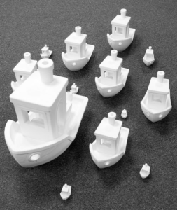
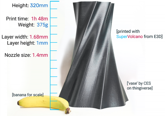
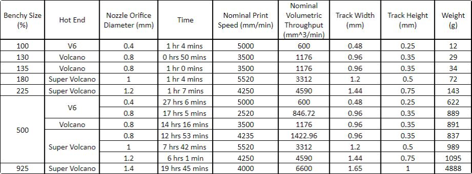
The following images from E3D shows the well known "Benchy" model which is popular for doing test prints. All of these Benchys were completed using the same settings in terms of speeds, acceleration, infill pecentage, perimeters and so on.
|
|
|
|
|
Benchy test prints with different hotends |
SuperVolcano example |
Table which shows the physical test values for each hotend |
|
Source of images and information: https://e3d-online.com/blog/2019/02/28/supervolcano |
||
Choosing the right flow helps getting consistent results. Polymer flow variation can be understood in the following way:
- increasing the line width, height or speed will increase flow
- more flow means that the polymer is less time in the melting zone, thus extruding slightly colder
- Combining the lower temperature and the higher shear stress generates a higher pressure
- a higher pressure puts more stress in the filament and extruder
- at some point, either the motor will start missing steps or the filament will grind, and the extrusion is not controlled anymore
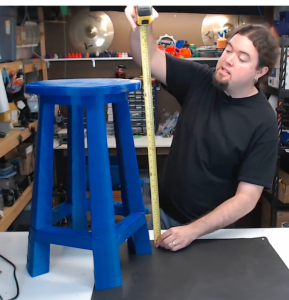
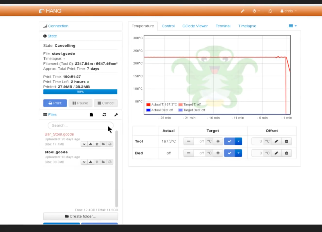
On the web there are different Hangprinter machine examples which were printed in big. Chris from Chris' Basement printed a large stool with 67 cm height and 40 cm in diameter. He used the following print parameters to make up the stool in 190 hours (= 24 days = 3.4 weeks = 72 working days á 8 hours = 10.3 weeks). The stool's weight is a total of 4.6 kg. This results in 24.21 g/hour material output. That means 193.7 g/working day (8 hours).
| Stool example | Octoprint evidence | Machine parameters |
|---|---|---|
|
|
|
|
The values from Chris and from E3D show that in total it's no problem to print between 25 and 250 gram of filament per hour (4888 g in 19.75 hours = 247.49 g / hour).
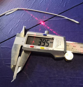
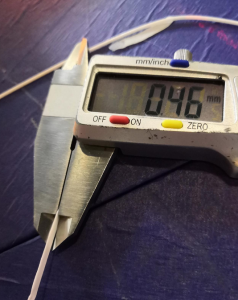
First tests with SuperVolcano Hotend 1.40 mm nozzle
Thinnest possible line using the 1.40 mm nozzle with tip platform diameter resulted in 3.95 mm width and 0.46 mm height.
Trikarus machine parameters
Trikarus Slicer profile contains the machine parameters. The profile is put at https://gitea.fablabchemnitz.de/vmario/Trikarus/src/branch/master/prusaslicer_profile
| parameter | value | hints |
| nozzle diameter | 1.40 mm | |
| platform shape | circle | |
| max. print height | get it by calibration → see Building basics, checks, maintenance |
|
| print diameter | 1000 mm (maximum physical value by the manufactured print platform) or 918.1 mm by thumb formula |
|
| max. feed XYZE |
|
|
| max. velocity XYZE | ? mm/s² | |
| max. jerk XYZE | ? mm/s | |
| regular (nominal) print speed | 1800 mm/min = 30 mm/s |
|
| max. volumetric throughput | 6600 mm³/min = 110 mm³/s |
|
| print speed for first layer | 15 mm/s |
|
| print travel speed | 130 mm/s |
|
|
typical layer (track) height |
1.00 mm |
|
| first layer height | 100% |
|
| first layer width | 1.57 mm |
|
| support material extrusion width | 1.00 mm |
|
| retraction vertical lift (Z hop) | 1.50 mm |
|
| retraction speed | 60 mm/s |
|
| retraction | 1.60 mm |
|
| coasting | disabled | |
| G-Code Flavor | Marlin |
|
PLA filament parameters
These settings highly depend on the bought filament (vendor, charge) and the print speed. Higher print speeds require higher heat intensity.
| parameter | value | hints | |
|---|---|---|---|
| 1 | filament diameter | 1.75 mm |
|
| 2 | extrusion multiplier | 1.0 |
|
| 3 | maximum hotend temperature | 260 °C |
|
| 4 | extrusion temperature for first layer | 205 - 210 °C |
|
| 5 | extrusion temperature for other layers | 195 - 240 °C |
|
| 6 | automatic cooling of the print | enabled | |
| 7 | min. cooling fan speed | 55 % |
|
| 8 | max. cooling fan speed | 100 % |
|
Slicing tips
Support border (brim)
Add support border for thin parts which are getting widened at upper layers. This helps to survive the print. The print head possibly kicks off the part from the platform. See the following video for failure example.
|
no support |
with support |
Print volume verification and line collisions
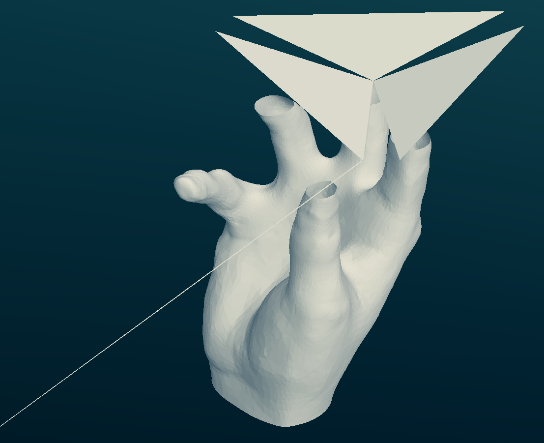
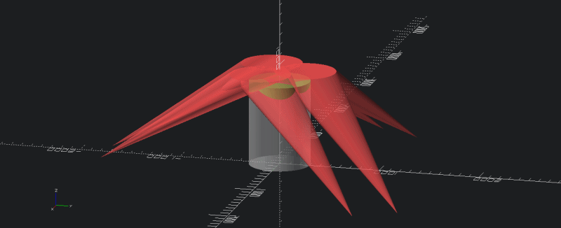
Currently there is no tool to determine if a given 3d model fits within "the print volume" of a given Hangprinter (with known calibration constants and dimensions, and given a cylinder with a known radius and height). Regular slicer engines do not support the special needs of Hangprinter build volume. The term "print volume" is more complicated for Hangprinters than for regular 3d printers. There exist a well defined "reachable volume". This reachable volume is interesting, but very rarely relevant. For Hangprinter most print volumes will be limited by lines touching the print and messing up the positioning of the effector. Lines may crash into previously printed material, so the reachable print area at a given layer depends on the shape of previously printed layers. The concept of a print volume exists, but it's shape is different for every print. In a more general situation where we don't print in 2d-layers, we would need to analyze the gcode directly, and consider every single move to be limited by every previous print move. Every single print move will cast unreachable "shadows" pointing from the anchor point and through the printed material. In regular 3d printer slicers like Cura, Simplify3D, MatterControl, IceSL or PrusaSlicer, the build volume is cubic or cylindric shape. Hangprinter shape is really different. More information about build volume can be found at What is a Hangprinter and how does it work?. The following illustration shows a possible line collision example for a case where the effector would move to the maximum left position.
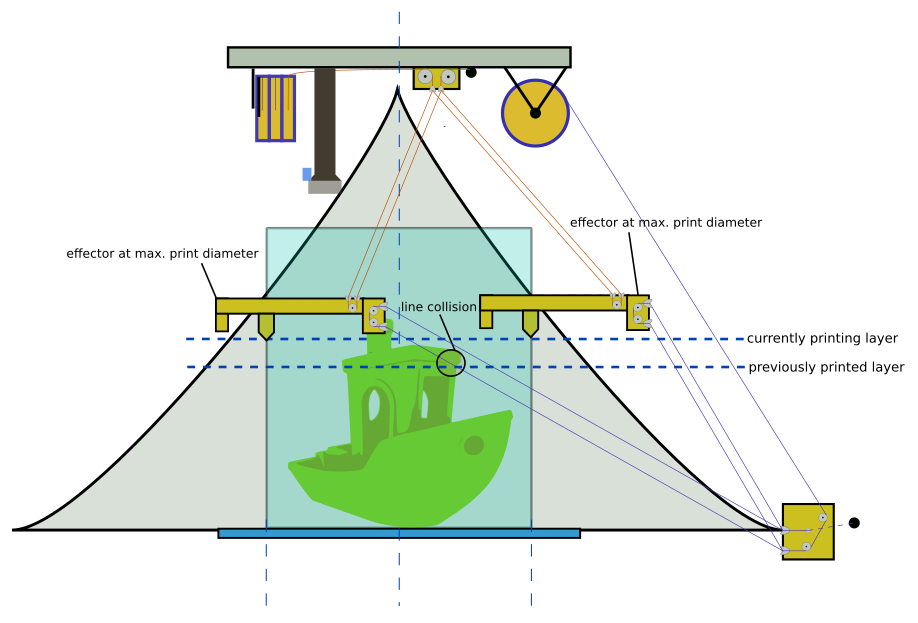
Simplified line collisision / print volume verification
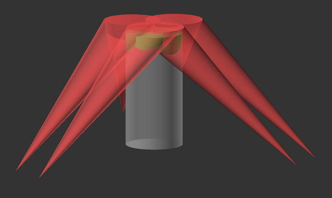
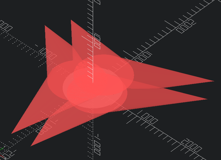
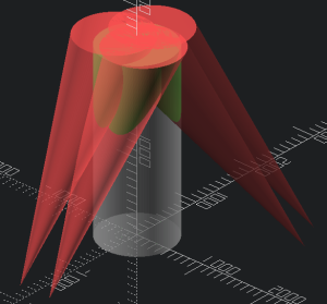
Given a Hangprinter with known calibration constants and dimensions, and given a cylinder with a known radius and height, analyze if we would have a line collision if the Hangprinter tried to print that cylinder. For a first catch of the possible print volume some OpenSCAD rough simulation exists. You can find that file at https://gitlab.com/tobben/hangprinter/-/blob/version_4_dev/src/simplified_print_volume_verification.scad. You will need to configure it accordingly with your own printer values. Trikarus' values can be found at RepRapFirmware and calculations and Building basics, checks, maintenance. There you can also find drawings which better illustrate the coordinate directions +-, anchor points (explicite coordinates A1/A2/B1/B2/C1/C2 and general A,B,C coordinates) and the offset used by the .scad file. The script generates collision preview for entered layer heights. It uses a cylindric shape - you can enter the values which you configured in your slicer profile too. The script is not complex enough to be used with 3d print model files. For this advanced purpose try https://gitlab.com/hangprinter/line-collision-detector
Parameters for the script
- A1/A2/B1/B2/C1/C2 coordinate offsets from A, B and C anchor positions
- layer height
- total count of layers
- print radius
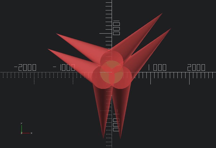
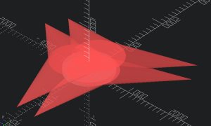
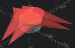
Some layer examples with
A_calib = [0, -1604, -114];
A_offset = [[-220, -135, 110],[ 220, -135, 110]];
A = [A_calib + A_offset[left],A_calib + A_offset[right]];
B_calib = [1312, 1271, -162];
B_offset = [[ 220, -135, 110],[ 0, 260, 110]];
B = [B_calib + B_offset[left],B_calib + B_offset[right]];
C_calib = [-1440, 741, -161];
C_offset = [[ 0, 260, 110],[-220, -135, 110]];
C = [C_calib + C_offset[left],C_calib + C_offset[right]];
layer_height = 1;
r = 1000/2;
| Layer 1 | Layer 100 | Layer 500 |
|
|
|
|
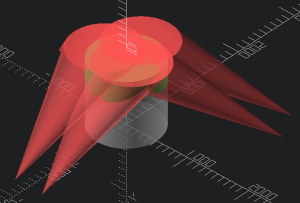
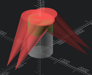
| Layer 1000 | Layer 1500 | Layer 2500 |
|
|
|
|
Animate it!
Show animation bar above output log
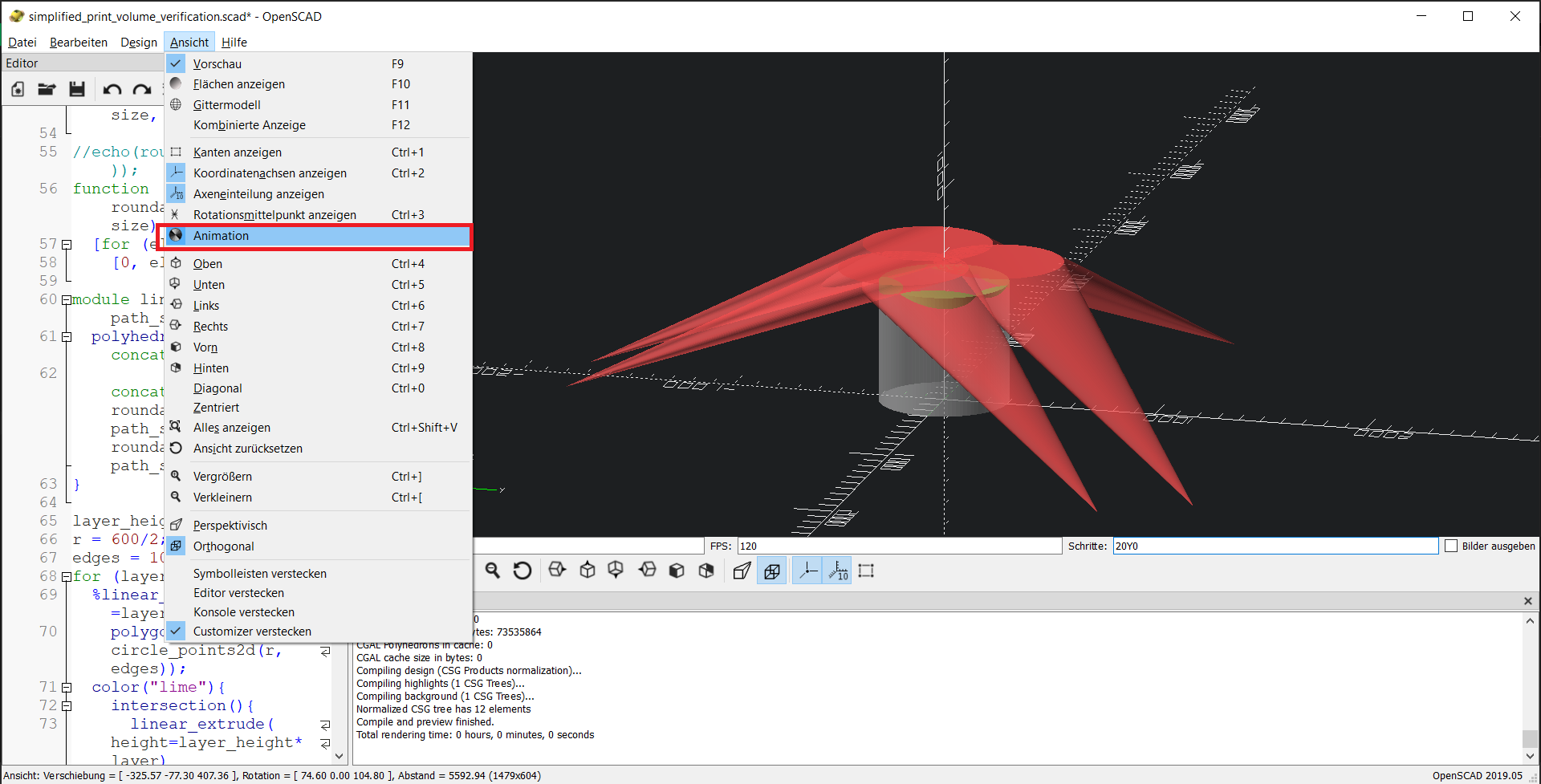
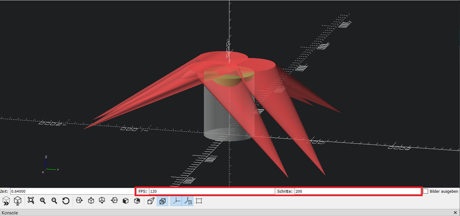
Enter frames per seconds value and steps
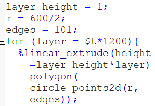
Put $t parameter into code
This parameter is the time parameter which will be incremented
View the animation
Advanced line collision/ print volume verification
This documentation is based on
- https://gitlab.com/hangprinter/line-collision-detector
- https://gitlab.com/hangprinter/linc/-/blob/f1282432a53a9c59042edb43716f4256b6de8caf/linc/params-example
- https://vitana.se/opr3d/tbear/2020.html
Prepare docker environment - we are installing on an Ubuntu machine
apt install docker docker.io
docker pull gcc
usermod -a -G docker $USER
reboot
Clone line collision detector repo and compile
This step finally generates a new docker container if successful
cd /opt
git clone https://gitlab.com/hangprinter/line-collision-detector.git
cd line-collision-detector
./build-docker.sh #The build process takes a lot of time. Might require 15 minutes or longer.
./docker-shell.sh  #starts the container - older releases of line collision detector always created new containers which could be seen with "docker ps -a".
Prepare the run command inside container
The run command is the final tool we need to do the collision analysis
#Inside the Docker container
cd /line-collision-detector
sudo git submodule update --init --recursive

#update git submodules (if required)
sudo git submodule update --remote --merge

#remove old build directory (if existent)
cd /line-collision-detector/linc/extern/spdlog/spdlog-1.6.0/
sudo rm -rf build/ #delete previous build dir

cd /line-collision-detector/
sudo ./faster.sh #compile

cd /line-collision-detector/linc
sudo b #make build using "b" command

#The line collision detector is ready to run:
cd /line-collision-detector/
sudo run
How to update line collision detector?
For updating we need to pull the latest changes from git repo and re-build the container and it's inner living.
cd /opt/line-collision-detector
git pull
./build-docker.sh
./docker-shell.sh

#now repeat the steps from "Prepare the run command inside container"
Create parameter file for your Hangprinter
For calculating collision we need to enter a set of coordinates first. This data set is stored in a file called "params" and used by the detector utility.
#ensure that docker container is running before trying to enter it
docker ps -a | grep line-collision-detector

DOCKER:/line-collision-detector# sudo vim params
effector-pivot-A1: ( -225.98, -162.47, 30.50)
effector-pivot-A2: ( 225.98, -162.47, 30.50)
effector-pivot-B1: ( 253.69, -114.47, 30.50)
effector-pivot-B2: ( 27.71, 276.94, 30.50)
effector-pivot-C1: ( -27.71, 276.94, 30.50)
effector-pivot-C2: ( -253.69, -114.47, 30.50)
anchor-pivot-A1: ( -225.98, -1328.47, 51.63)
anchor-pivot-A2: ( 225.98, -1328.47, 51.63)
anchor-pivot-B1: ( 1263.69, 470.53, 55.76)
anchor-pivot-B2: ( 1037.71, 861.94, 55.76)
anchor-pivot-C1: (-1042.71, 854.94, 59.05)
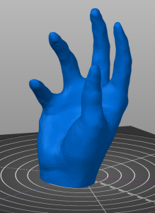
anchor-pivot-C2: (-1268.69, 463.53, 59.05)Prepare the STL model
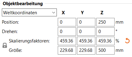
To do the analysis we need to adjust the STL model file:
- position on the bed (coordinate system)
- scaling / desired size
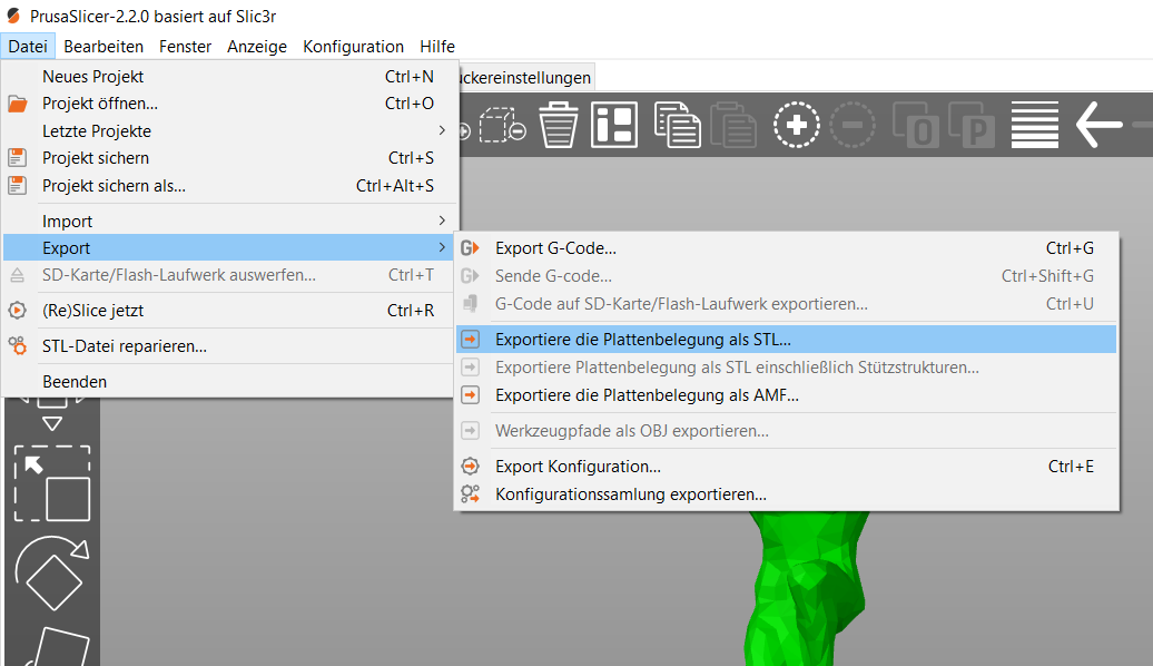
We can adjust the scale and re-export the STL file using PrusaSlicer with ease:
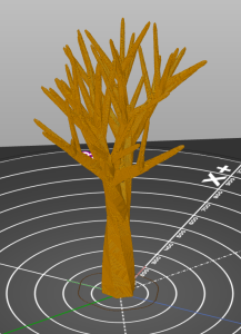
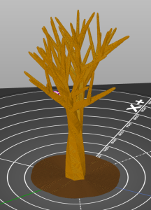
Perform the collision analysis
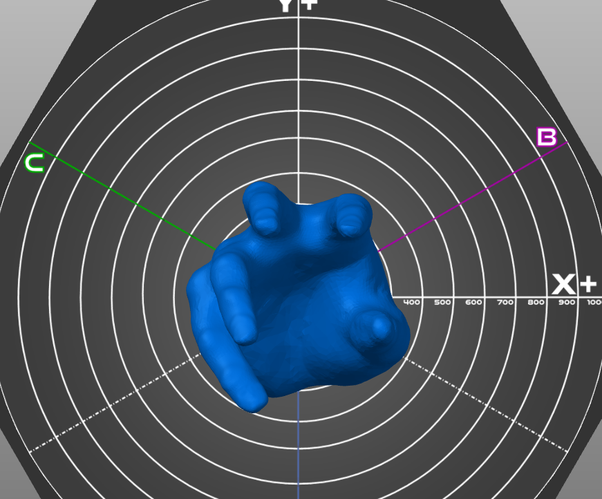
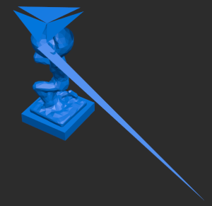
To simulate collision we need to put an STL file into the directory /opt/line-collision-detector (outside the container). The special command inside the docker-shell.sh file will map this directory to grant access to it within the docker container. The calculation takes less or more time (less seconds up to minutes) belonging to the given layer height, model size and computation power of your node. In case a collision happens and we use the -o option to create a debug file (STL) file, we can view this collision.
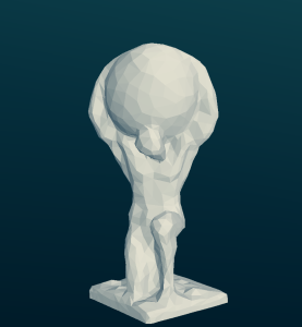
First example (Statue of Atlas):
DOCKER:/line-collision-detector# sudo run ./atlas.stl params -l 1 #using the params file and 1 mm layer height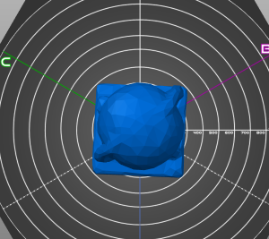
OCKER:/line-collision-detector# sudo run ./Hand\ 2_400.stl params -l 1
No collision detected
DOCKER:/line-collision-detector# sudo run ./Hand\ 2_500.stl params -l 1
No collision detected
DOCKER:/line-collision-detector# sudo run ./Hand\ 2_600.stl params -l 1
No collision detected
DOCKER:/line-collision-detector# sudo run ./Hand\ 2_700.stl params -l 1
Collision detected at z=375.815
DOCKER:/line-collision-detector# sudo run ./Hand\ 2_650.stl params -l 1
Collision detected at z=350.815
DOCKER:/line-collision-detector# sudo run ./Hand\ 2_630.stl params -l 1
Collision detected at z=461.605
DOCKER:/line-collision-detector# sudo run ./Hand\ 2_615.stl params -l 1
No collision detected
DOCKER:/line-collision-detector# sudo run ./Hand\ 2_615.stl params -l 0.8
No collision detected
Second example (Hand):