# Bills of material and hardware compenent features

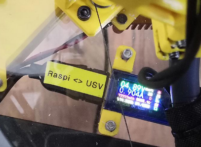
# Ceiling module |  AT34 USB Tester

<iframe height="809" id="bkmrk--1" src="https://wiki.stadtfabrikanten.org/pdfjs/web/viewer.html?file=https://wiki.stadtfabrikanten.org/attachments/137" style="width: 539px; height: 809px;" title="PDF viwer" width="539"></iframe>

[![grafik.png](https://wiki.stadtfabrikanten.org/uploads/images/gallery/2026-06/scaled-1680-/YQs6SoxyY2ibT4DH-grafik.png)](https://wiki.stadtfabrikanten.org/uploads/images/gallery/2026-06/YQs6SoxyY2ibT4DH-grafik.png)

This is used to check the voltage of Raspberry Pi and to validate occuring undervoltage happenings. It's a really useful helper.

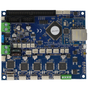
# Ceiling module |  Duet 2 Ethernet v1.04

[![grafik.png](https://wiki.stadtfabrikanten.org/uploads/images/gallery/2026-06/scaled-1680-/AoGaSFyk34yI2do7-grafik.png)](https://wiki.stadtfabrikanten.org/uploads/images/gallery/2026-06/AoGaSFyk34yI2do7-grafik.png) [![grafik.png](https://wiki.stadtfabrikanten.org/uploads/images/gallery/2026-06/scaled-1680-/l7sicPYcukxeSOHj-grafik.png)
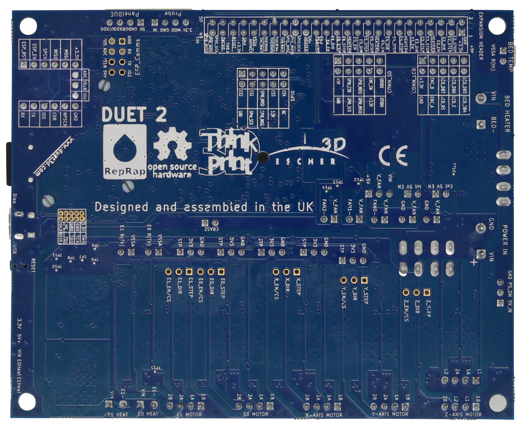
](https://wiki.stadtfabrikanten.org/uploads/images/gallery/2026-06/l7sicPYcukxeSOHj-grafik.png) [![grafik.png](https://wiki.stadtfabrikanten.org/uploads/images/gallery/2026-06/scaled-1680-/PhXhtlsvVtbpqAQ5-grafik.png)
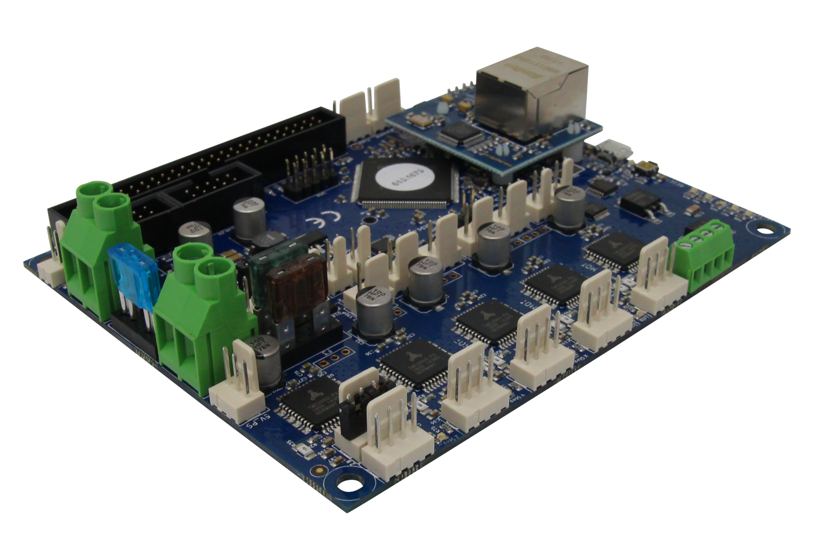
](https://wiki.stadtfabrikanten.org/uploads/images/gallery/2026-06/PhXhtlsvVtbpqAQ5-grafik.png) [![grafik.png](https://wiki.stadtfabrikanten.org/uploads/images/gallery/2026-06/scaled-1680-/qAUX8Ra4EUHjeIhl-grafik.png)
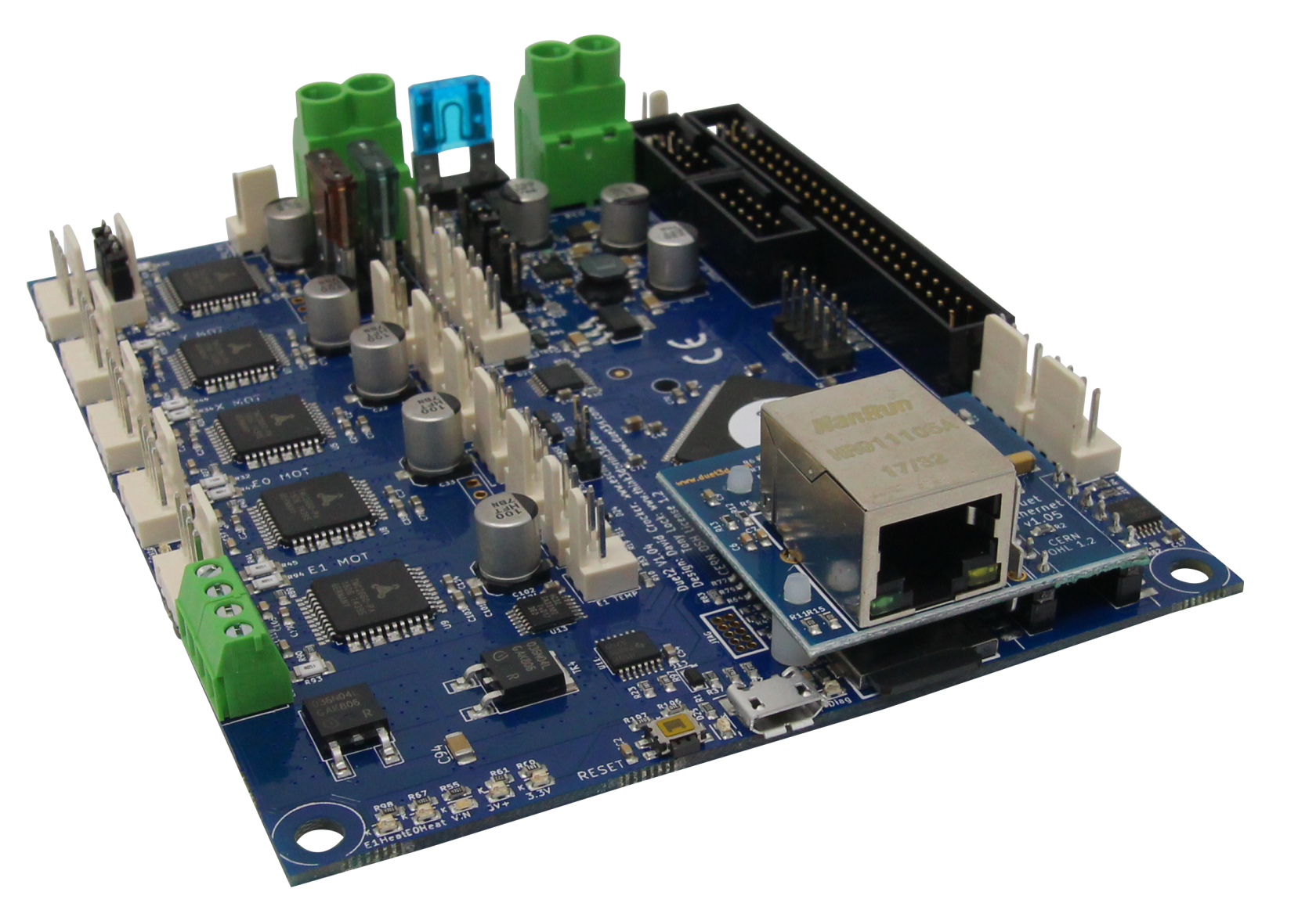
](https://wiki.stadtfabrikanten.org/uploads/images/gallery/2026-06/qAUX8Ra4EUHjeIhl-grafik.png) [![grafik.png](https://wiki.stadtfabrikanten.org/uploads/images/gallery/2026-06/scaled-1680-/92s7tte8Pa2uCiiO-grafik.png)
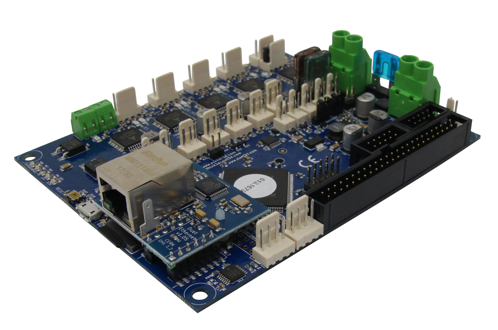
](https://wiki.stadtfabrikanten.org/uploads/images/gallery/2026-06/92s7tte8Pa2uCiiO-grafik.png)

[![grafik.png](https://wiki.stadtfabrikanten.org/uploads/images/gallery/2026-06/scaled-1680-/RkvpzXBea2sJAib5-grafik.png)](https://wiki.stadtfabrikanten.org/uploads/images/gallery/2026-06/RkvpzXBea2sJAib5-grafik.png) [![grafik.png](https://wiki.stadtfabrikanten.org/uploads/images/gallery/2026-06/scaled-1680-/mpoiOCbSFyS4rinN-grafik.png)
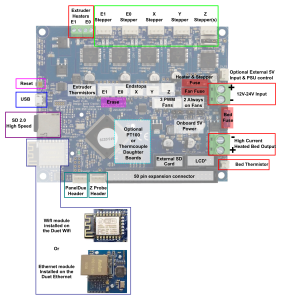
](https://wiki.stadtfabrikanten.org/uploads/images/gallery/2026-06/mpoiOCbSFyS4rinN-grafik.png)

<iframe height="450vh" id="bkmrk--2" src="https://wiki.stadtfabrikanten.org/pdfjs/web/viewer.html?file=https://wiki.stadtfabrikanten.org/attachments/158" title="PDF viwer" width="100%"></iframe>

<iframe height="450vh" id="bkmrk--3" src="https://wiki.stadtfabrikanten.org/pdfjs/web/viewer.html?file=https://wiki.stadtfabrikanten.org/attachments/159" title="PDF viwer" width="100%"></iframe>

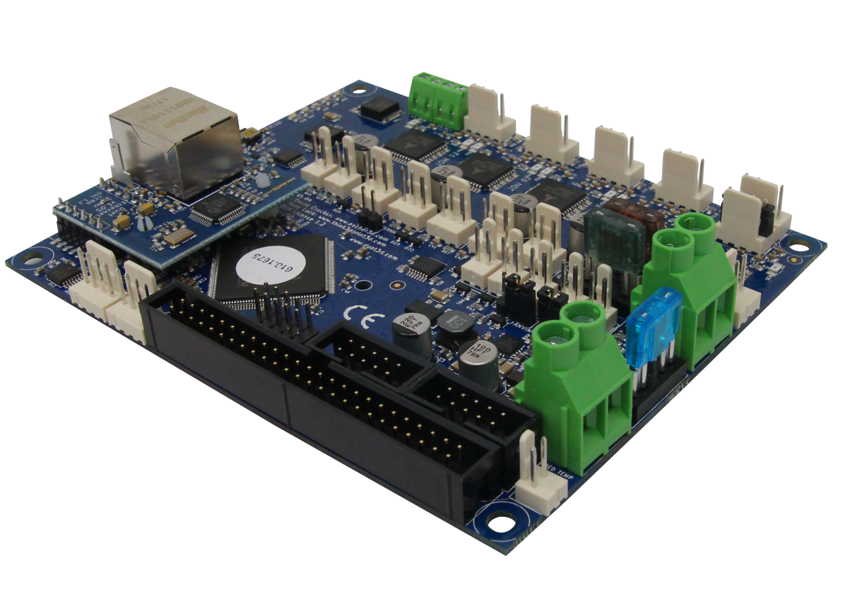
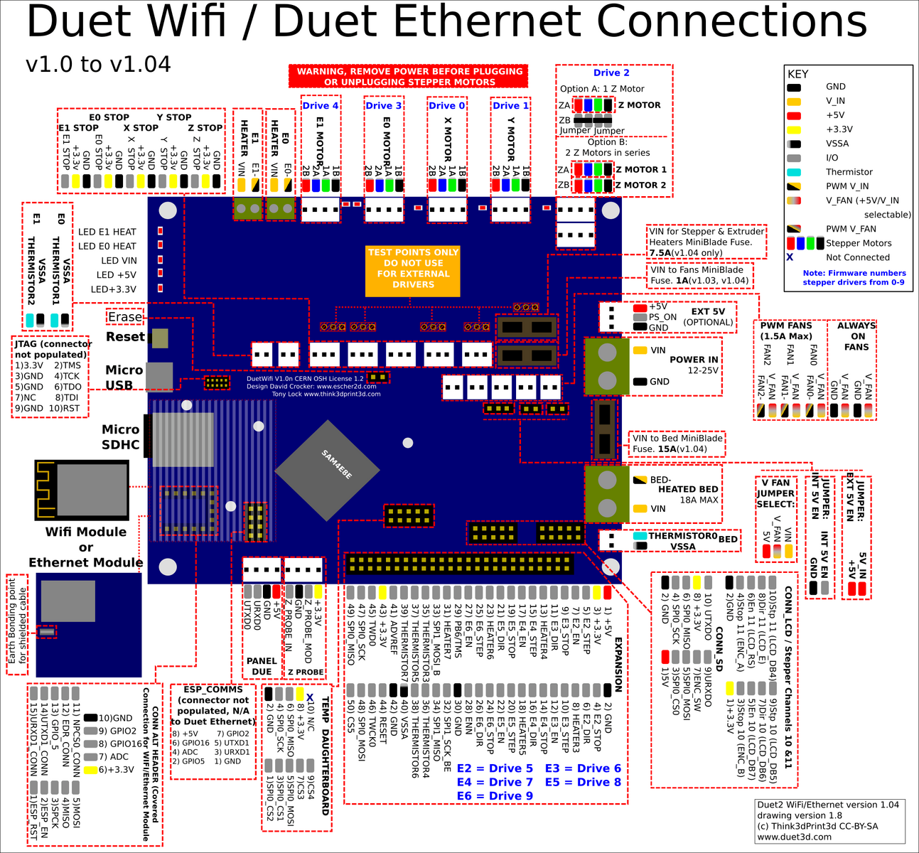
# Description (copied from [https://www.duet3d.com/DuetEthernet](https://www.duet3d.com/DuetEthernet))

This is the latest PCB revision of the Duet 2 Ethernet, v1.04.

The Duet 2 Ethernet is an advanced 32 bit electronics board for the control of 3D printers and other CNC machines. It has the same features as the [Duet 2 Wifi](https://www.duet3d.com/DuetWifi), other than providing ethernet connectivity rather than Wifi, a [full feature description is available on our documentation](https://duet3d.dozuki.com/Wiki/Hardware_Overview), in summary:

- Powerful 32 Bit Processor
- Dedicated ethernet module.
- Super quiet TMC2660 stepper drivers, up to 256 microstepping.
- High speed SD card and support for a second SD external card if required.
- Dual extruders on the main board, up to 5 more extruders on the [expansion board](https://www.duet3d.com/Duex5).
- High Power rating: Each stepper driver is capable of 2.8A motor current, currently limited in software to 2.4A. The bed heater channel is specifically designed for high current (18A).
- Connect via PC, tablet or smartphone on the same network to the on board web interface.
- Setup your printer and update the firmware through the [web interface](https://duet3d.com/wiki/Duet_Web_Control).
- All common 3D printer geometries are supported
- Expandable up to 7 extruders with Firmware support for mixing nozzles and remapping axes to use high power external drivers.
- Support for the [PanelDue](https://duet3d.com/wiki/PanelDue): a full colour graphic touch screen.
- Support for [DC42’s IR Z probe](https://www.duet3d.com/IRProbe) and the [Duet3D Smart Effector](https://www.duet3d.com/DeltaSmartEffector) for delta printers.
- Provided with Molex compatible plugs and crimps as well as ferrules for power and heater terminals.

The Duet 2 Ethernet can have [Thermistors ](https://www.duet3d.com/e3d_Thermistor)connected directly, alternatively we have two different temperature sensing daughterboards available:

- [PT100 Temperature daughterboard](https://www.duet3d.com/PT100_DaughterBoard)
- [Thermocouple temperature daughterboard.](https://www.duet3d.com/TC_K_DaughterBoard)

We also supply genuine e3d PT100 and thermocouple sensors compatible with their range of hotends:

- [PT100 sensor](https://www.duet3d.com/PT100Sensor_2wire)
- [Type K Thermocouple sensor.](https://www.duet3d.com/TypeK_TC)

# Wiring

[![grafik.png](https://wiki.stadtfabrikanten.org/uploads/images/gallery/2026-06/scaled-1680-/rnwHF5OVwOkHff9p-grafik.png)](https://wiki.stadtfabrikanten.org/uploads/images/gallery/2026-06/rnwHF5OVwOkHff9p-grafik.png)

## Replacement parts

[https://duet3d.dozuki.com/Wiki/Connector\_and\_spare\_part\_numbers](https://duet3d.dozuki.com/Wiki/Connector_and_spare_part_numbers)

## Fan mosfet

If you short out a PWM fan, the fan driver mosfet will burn out. The replacement part number is **PMV40UN2** or **PMV40UN2R** which is available from the usual electronic component distributors such as Farnell/Newark/element14, Digikey, Mouser and RS. You can also use type **PMV20XNER** or **AO3400A** which have a higher peak current rating. The component identifiers on the board are:

- Fan 0 mosfet: TR5
- Fan 1 mosfet: TR9
- Fan 2 mosfet: TR1

To remove the old mosfet, you will need either a hot air desoldering tool with a small nozzle, or low melting point solder such as ChipQuik . If using hot air, use a shield made from e.g. corrugated cardboard covered with Kapton tape to shield connectors and other plastic components from the hot air. The new mosfet can be soldered in place using a fine-tipped soldering iron, or by putting a little no-clean flux on the pads, placing the new mosfet on top, and using hot air again. Hot air soldering/desoldering is easier if you heat the whole board to about 100-125C on an electric hotplate.

## Heater MOSFETs

Note when removing any of the heater MOSFETs there is significant heat-sinking into the copper of the board. A combination of hot air rework, Chipquick, and a heated plate may be needed to remove one successfully.

- Bed Heater 
    - TR2: this is an IPD036N04LGBTMA1
- E0, E1 Heaters 
    - TR3, TR4: this is an AOD4184A (you an also use IPD036N04LGBTMA1)
- The small green component bearing the letters 'bF' is the self-resetting fuse, and the component with stripes is the optional 10K resistor. A piece of Kapton tape was put on the board first to provide additional insulation.

## Mini blade fuses

- 1A mini auto blade fuse protecting the fan circuits when the fan voltage selection jumper is in the VIN position. You can increase the fuse rating to 2A or even 3A if your fans, air pumps etc. draw more than 1A in total.
- 15A fuse for the bed heater circuit
- 7.5A fuse for everything else

## TFT panel backlight inverter IC

If the TFT panel of a **non-integrated** PanelDue assembly suddenly refuses to light up, chances are that the backlight inverter chip has failed. This is a 6-pin chip marked L6CE or L6EN or L6GE or similar (the Pin 1 marking bar can easily be mistaken for a letter I in front of the L). The part number is MP3202DJ. It is available from RS Components, Digikey and Mouser, and also on eBay and Ali Express.

### Other things

<p class="callout warning">Duet has no support for POE and will be fried if it get's connected to passive POE like [Shanqiu Mini UPS FX5-48 / Vultec Continuity UPS30PW-DC](https://old.stadtfabrikanten.org/pages/createpage.action?spaceKey=TH&title=Shanqiu+Mini+UPS+FX5-48+%2F+Vultec+Continuity+UPS30PW-DC&linkCreation=true&fromPageId=56623211) has got.</p>

# Ceiling module |  Gyroscope and acceleration sensor GY-521 (MPU6050)

[![grafik.png](https://wiki.stadtfabrikanten.org/uploads/images/gallery/2026-06/scaled-1680-/pe3tw8HBlBUNWatM-grafik.png)
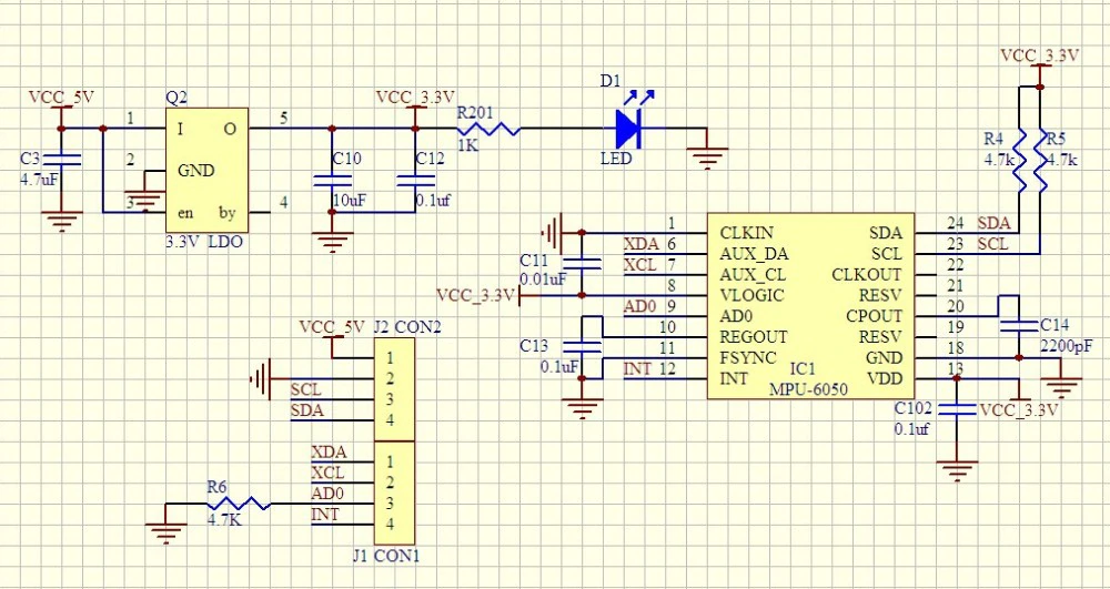
](https://wiki.stadtfabrikanten.org/uploads/images/gallery/2026-06/pe3tw8HBlBUNWatM-grafik.png) [![grafik.png](https://wiki.stadtfabrikanten.org/uploads/images/gallery/2026-06/scaled-1680-/eqQxF2Ex4WN2JuHw-grafik.png)
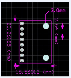
](https://wiki.stadtfabrikanten.org/uploads/images/gallery/2026-06/eqQxF2Ex4WN2JuHw-grafik.png) [![grafik.png](https://wiki.stadtfabrikanten.org/uploads/images/gallery/2026-06/scaled-1680-/P3W3z6SxflVfS7r5-grafik.png)
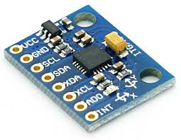
](https://wiki.stadtfabrikanten.org/uploads/images/gallery/2026-06/P3W3z6SxflVfS7r5-grafik.png)

<iframe height="450vh" id="bkmrk--2" src="https://wiki.stadtfabrikanten.org/pdfjs/web/viewer.html?file=https://wiki.stadtfabrikanten.org/attachments/149" title="PDF viwer" width="100%"></iframe>

<iframe height="450vh" id="bkmrk--3" src="https://wiki.stadtfabrikanten.org/pdfjs/web/viewer.html?file=https://wiki.stadtfabrikanten.org/attachments/150" title="PDF viwer" width="100%"></iframe>

<iframe height="450vh" id="bkmrk--4" src="https://wiki.stadtfabrikanten.org/pdfjs/web/viewer.html?file=https://wiki.stadtfabrikanten.org/attachments/151" title="PDF viwer" width="100%"></iframe>

## MPU6050 pin configuration

<div class="table-wrap" id="bkmrk-pin-number-pin-name-"><table><colgroup><col></col><col></col><col></col></colgroup><thead><tr><td>**Pin number**

</td><td>**Pin name**

</td><td>**Description**

</td></tr></thead><tbody><tr><td>1

</td><td>Vcc

</td><td>Provides power for the module, can be +3V to +5V. Typically +5V is used

</td></tr><tr><td>2

</td><td>Ground

</td><td>Connected to Ground of system

</td></tr><tr><td>3

</td><td>Serial Clock (SCL)

</td><td>Used for providing clock pulse for I2C Communication

</td></tr><tr><td>4

</td><td>Serial Data (SDA)

</td><td>Used for transferring Data through I2C communication

</td></tr><tr><td>5

</td><td>Auxiliary Serial Data (XDA)

</td><td>Can be used to interface other I2C modules with MPU6050. It is optional

</td></tr><tr><td>6

</td><td>Auxiliary Serial Clock (XCL)

</td><td>Can be used to interface other I2C modules with MPU6050. It is optional

</td></tr><tr><td>7

</td><td>AD0

</td><td>If more than one MPU6050 is used a single MCU, then this pin can be used to vary the address

</td></tr><tr><td>8

</td><td>Interrupt (INT)

</td><td>Interrupt pin to indicate that data is available for MCU to read.

</td></tr></tbody></table>

</div>## MPU6050 features

- MEMS 3-aixs accelerometer and 3-axis gyroscope values combined
- Power Supply: 3-5V
- Communication : I2C protocol
- Built-in 16-bit ADC provides high accuracy
- Built-in DMP provides high computational power (Digital Motion Processor) - reduces the load for the microcontroller (like the Arduino)
- Can be used to interface with other IIC devices like magnetometer
- Configurable IIC Address
- In-built Temperature sensor

## Key words

- <span class="placeholder-inline-tasks">gyro</span>
- <span class="placeholder-inline-tasks">Inclinometer</span>
- <span class="placeholder-inline-tasks">Beschleunigungssensor</span>
- <span class="placeholder-inline-tasks">Neigungssensor</span>
- <span class="placeholder-inline-tasks">gyroscope</span>
- <span class="placeholder-inline-tasks">accelerometer</span>
- <span class="placeholder-inline-tasks">tilt sensor</span>

## Enable I2C on Raspberry Pi

```bash
vim /boot/config.txt
```

<div class="code panel pdl conf-macro output-block" data-hasbody="true" data-macro-name="code" id="bkmrk--5" style="border-width: 1px;"><div class="codeContent panelContent pdl"><div><div class="syntaxhighlighter sh-django  bash" id="bkmrk--6"></div></div></div></div><div class="code panel pdl conf-macro output-block" data-hasbody="true" data-macro-name="code" id="bkmrk--7" style="border-width: 1px;"><div class="codeContent panelContent pdl"><div><div class="syntaxhighlighter sh-django  bash" id="bkmrk--8"></div></div></div></div>```bash
dtparam=i2c_arm=on
```

```bash
vim /etc/modules
```

<div class="code panel pdl conf-macro output-block" data-hasbody="true" data-macro-name="code" id="bkmrk--9" style="border-width: 1px;"><div class="codeContent panelContent pdl"><div><div class="syntaxhighlighter sh-django  bash" id="bkmrk--10"></div></div></div></div><div class="code panel pdl conf-macro output-block" data-hasbody="true" data-macro-name="code" id="bkmrk--11" style="border-width: 1px;"><div class="codeContent panelContent pdl"><div><div class="syntaxhighlighter sh-django  bash" id="bkmrk--12"></div></div></div></div><div class="code panel pdl conf-macro output-block" data-hasbody="true" data-macro-name="code" id="bkmrk--13" style="border-width: 1px;"><div class="syntaxhighlighter sh-django  bash"></div></div>```bash
i2c-bcm2708
i2c-dev
```

Finde installierte I2C Module.

```bash
i2cdetect -y 1 #returns 0x68
```

<div class="code panel pdl conf-macro output-block" data-hasbody="true" data-macro-name="code" id="bkmrk--14" style="border-width: 1px;"><div class="codeContent panelContent pdl"><div><div class="syntaxhighlighter sh-django  bash" id="bkmrk--15"></div></div></div></div><span lang="en">By default, each MPU 6050 has the same address with bit 0x68. An enable signal can be sent via pin "AD0", which redirects the sensor to 0x69. Pin AD0 got a fixed solderding to give the secondary address 0x69.</span>

[![grafik.png](https://wiki.stadtfabrikanten.org/uploads/images/gallery/2026-06/scaled-1680-/rYLN1tdKEE3rLEju-grafik.png)](https://wiki.stadtfabrikanten.org/uploads/images/gallery/2026-06/rYLN1tdKEE3rLEju-grafik.png)

```
i2cdetect -y 1 #now returns 0x69
```

## Debugging

<div class="code panel pdl conf-macro output-block" data-hasbody="true" data-macro-name="code" id="bkmrk--17" style="border-width: 1px;"><div class="codeContent panelContent pdl"><div><div class="syntaxhighlighter sh-django  bash" id="bkmrk--18"></div></div></div></div>Sometimes the gyros do not properly work when connected. While working within Trikarus project, multiple errors occured. There were errors thrown like "OSError: \[Errno 121\] Remote I/O error - has occurred". Especially making DMP work was a horror trip because it threw a lot of errors while with regular raw values this was not the big deal. It seems to be a problem with long wire, unstable clock frequency and pullup resistors.

There are multiple solutions to fix the situation.

- check wiring quality and wire length/isolation
- check the supply voltage vor MPU 6050. It requires nominally 3.3 V  
    
    - VDD → 2.375 V - 3.46 V
    - VLOGIC → 1.71 V to VDD
- check / adjust the I²C bus frequency of Raspberry Pi (have a look at [<span>https://github.com/fivdi/i2c-bus/blob/master/doc/raspberry-pi-i2c.md</span>)](https://github.com/fivdi/i2c-bus/blob/master/doc/raspberry-pi-i2c.md))
    
    
    - ```bash
         show recent baudrate
        cat /sys/module/i2c_bcm2708/parameters/baudrate
         
        # adjust baudrate temporarily - set it to 10.000
        modprobe i2c_bcm2708 baudrate=10000
        cat /sys/module/i2c_bcm2708/parameters/baudrate
         
        # if you want to edit it permanently edit boot config by your needs - maximum baudrate is 400.000, default is 100.000
        vim /boot/config.txt
        dtparam=i2c_arm=on
        i2c_arm_baudrate=400000
        ```
- check I²C communication by i2c dumping
    
    
    - ```bash
        while i2cdump -y -r 0-7 1 0x68 c; do sleep 1; done
        while i2cdump -y -r 0-7 1 0x69 c; do sleep 1; done
        ```
- maybe add some delay after setting smbus.SMBus(1) to settle. A lot of people set some wait time, e.g. 1 second
- if there is a second MPU 6050 connected please check if there are problems while addressing them. Check if AD0 is set to 1 accordingly and if AD0 is grounded correctly. Check the devices separetely by disconnecting one of both to ensure that they work in single mode correctly.

## Monitoring → [MPU 6050 (GY-521) Gyro + Accelerometer monitoring](https://old.stadtfabrikanten.org/pages/viewpage.action?pageId=65405374)

## C++ script to read the data (quickly show the output to console)

At [https://github.com/richardghirst/PiBits](https://github.com/richardghirst/PiBits) there's a good example to use MPU6050 with raw data or filterered by DMP.

## Configure and build

```bash
apt install libgtkmm-3.0-dev
git clone https://github.com/richardghirst/PiBits.git
cd MPU6050-Pi-Demo/
 
#adjust I2C basics
vim I2Cdev.cpp #change all "/dev/i2c-0" to "/dev/i2c-1"
 
#to change I2C 0x69 or 0x69 change MPU6050 accelgyro; to MPU6050 accelgyro(MPU6050_ADDRESS_AD0_HIGH);
vim demo_raw.cpp
 
#to change I2C 0x69 or 0x69 change MPU6050 mpu; to MPU6050 mpu(MPU6050_ADDRESS_AD0_HIGH);
vim demo_dmp.cpp
 
make
```

<div class="rwui_steps conf-macro output-block" data-hasbody="true" data-macro-name="ui-steps" id="bkmrk--19"><div class="rwui_step conf-macro output-block" data-hasbody="true" data-macro-name="ui-step"><div class="rwui_item_content"><div class="code panel pdl conf-macro output-block" data-hasbody="true" data-macro-name="code" style="border-width: 1px;"><div class="codeContent panelContent pdl"><div><div class="syntaxhighlighter sh-django  bash" id="bkmrk--20"></div></div></div></div></div></div><div class="rwui_step conf-macro output-block" data-hasbody="true" data-macro-name="ui-step"></div></div>## Run

```bash
#raw mode
./demo_raw
 
 
#DMP mode
./demo_dmp
#this will sometimes fail with
Initializing I2C devices...
Testing device connections...
MPU6050 connection successful
Initializing DMP...
DMP Initialization failed (code 1)
 
#You can also run gdb to debug:
gdb ./demo_dmp
#then enter "run"
```

<div class="rwui_steps conf-macro output-block" data-hasbody="true" data-macro-name="ui-steps" id="bkmrk--21"><div class="rwui_step conf-macro output-block" data-hasbody="true" data-macro-name="ui-step"><div class="rwui_item_content"><div class="code panel pdl conf-macro output-block" data-hasbody="true" data-macro-name="code" style="border-width: 1px;"><div class="codeContent panelContent pdl"><div><div class="syntaxhighlighter sh-django  bash" id="bkmrk--22"></div></div></div></div></div></div></div>

# Ceiling module |  Raspberry Pi 3 B

[![grafik.png](https://wiki.stadtfabrikanten.org/uploads/images/gallery/2026-06/scaled-1680-/cLWh7qQRE0t8pL8f-grafik.png)](https://wiki.stadtfabrikanten.org/uploads/images/gallery/2026-06/cLWh7qQRE0t8pL8f-grafik.png)

<iframe height="450vh" id="bkmrk--2" src="https://wiki.stadtfabrikanten.org/pdfjs/web/viewer.html?file=https://wiki.stadtfabrikanten.org/attachments/156" title="PDF viwer" width="100%"></iframe>

<iframe height="450vh" id="bkmrk--3" src="https://wiki.stadtfabrikanten.org/pdfjs/web/viewer.html?file=https://wiki.stadtfabrikanten.org/attachments/157" title="PDF viwer" width="100%"></iframe>

# Ceiling module |  Shanqiu Mini UPS FX5-48 / Vultec Continuity UPS30PW-DC

[![grafik.png](https://wiki.stadtfabrikanten.org/uploads/images/gallery/2026-06/scaled-1680-/ibwQpvqU1pG4aTSx-grafik.png)](https://wiki.stadtfabrikanten.org/uploads/images/gallery/2026-06/ibwQpvqU1pG4aTSx-grafik.png) [![grafik.png](https://wiki.stadtfabrikanten.org/uploads/images/gallery/2026-06/scaled-1680-/tBxUDxmyb6cERKBs-grafik.png)](https://wiki.stadtfabrikanten.org/uploads/images/gallery/2026-06/tBxUDxmyb6cERKBs-grafik.png) [![grafik.png](https://wiki.stadtfabrikanten.org/uploads/images/gallery/2026-06/scaled-1680-/OhhzifE114nQawpl-grafik.png)](https://wiki.stadtfabrikanten.org/uploads/images/gallery/2026-06/OhhzifE114nQawpl-grafik.png)

[![grafik.png](https://wiki.stadtfabrikanten.org/uploads/images/gallery/2026-06/scaled-1680-/h5pCt2jZIIN2KSWA-grafik.png)](https://wiki.stadtfabrikanten.org/uploads/images/gallery/2026-06/h5pCt2jZIIN2KSWA-grafik.png) [![grafik.png](https://wiki.stadtfabrikanten.org/uploads/images/gallery/2026-06/scaled-1680-/nHUXpoIXXPp2XomH-grafik.png)](https://wiki.stadtfabrikanten.org/uploads/images/gallery/2026-06/nHUXpoIXXPp2XomH-grafik.png) [![grafik.png](https://wiki.stadtfabrikanten.org/uploads/images/gallery/2026-06/scaled-1680-/Q2NlagfouYDmiX7M-grafik.png)](https://wiki.stadtfabrikanten.org/uploads/images/gallery/2026-06/Q2NlagfouYDmiX7M-grafik.png) [![grafik.png](https://wiki.stadtfabrikanten.org/uploads/images/gallery/2026-06/scaled-1680-/mKn79KzdHJh187sB-grafik.png)](https://wiki.stadtfabrikanten.org/uploads/images/gallery/2026-06/mKn79KzdHJh187sB-grafik.png)

<iframe height="450vh" id="bkmrk--2" src="https://wiki.stadtfabrikanten.org/pdfjs/web/viewer.html?file=https://wiki.stadtfabrikanten.org/attachments/146" title="PDF viwer" width="100%"></iframe>

<iframe height="450vh" id="bkmrk--3" src="https://wiki.stadtfabrikanten.org/pdfjs/web/viewer.html?file=https://wiki.stadtfabrikanten.org/attachments/147" title="PDF viwer" width="100%"></iframe>

<iframe height="450vh" id="bkmrk--4" src="https://wiki.stadtfabrikanten.org/pdfjs/web/viewer.html?file=https://wiki.stadtfabrikanten.org/attachments/148" title="PDF viwer" width="100%"></iframe>

## Notes

- There are different versions of the UPS ("USV" is german short name for this) on the market. Shanqiu Mini USV FX5-48 and Vultec Continuity UPS30PW-DC are nearly the same models except different color, POE wattage and branding. Both come with 5 V USB connector which allows up to 2. 0 A output.
- product link: [https://www.amazon.de/VulTech-Continuity-Serie-DC-Watt/dp/B07TBKVLKX](https://www.amazon.de/VulTech-Continuity-Serie-DC-Watt/dp/B07TBKVLKX)
- <span lang="en">**Warning**: The UPS does not have a POE with sensing technology. Devices that do not have POE support can suffer damage. I have tested it on my USB network card. This started after about 30 seconds with intense smoke formation. I quickly released the connection by plugging off again. For this reason, I 3d printed 2 adapter pieces to seal the POE-LAN ​​sockets (some kind of disallowed usage).</span> → [https://m.drivesncontrols.com/news/fullstory.php/aid/4494/PoE\_extensions\_\_91can\_damage\_non-PoE\_equipment\_92.html](https://m.drivesncontrols.com/news/fullstory.php/aid/4494/PoE_extensions__91can_damage_non-PoE_equipment_92.html)

# Ceiling module |  Smart Stepper rev 1/20/2019 by MisfitTech

## Electrical Components on the MisfitTech Smart Stepper Board

- Allegro 4954LPT DMOS PWM Motor Driver
- AMS AS5047D High Speed Position Sensor
- Atmel ATSAMD21G18 Cortex MCU

[![grafik.png](https://wiki.stadtfabrikanten.org/uploads/images/gallery/2026-06/scaled-1680-/TEhmxuCuADyGw2jT-grafik.png)](https://wiki.stadtfabrikanten.org/uploads/images/gallery/2026-06/TEhmxuCuADyGw2jT-grafik.png) [![grafik.png](https://wiki.stadtfabrikanten.org/uploads/images/gallery/2026-06/scaled-1680-/LOGAwX6yCQlOpLkK-grafik.png)](https://wiki.stadtfabrikanten.org/uploads/images/gallery/2026-06/LOGAwX6yCQlOpLkK-grafik.png) [![grafik.png](https://wiki.stadtfabrikanten.org/uploads/images/gallery/2026-06/scaled-1680-/EwBreNJcv2ftirYl-grafik.png)](https://wiki.stadtfabrikanten.org/uploads/images/gallery/2026-06/EwBreNJcv2ftirYl-grafik.png)

[![grafik.png](https://wiki.stadtfabrikanten.org/uploads/images/gallery/2026-06/scaled-1680-/biLhbFdyzQjighDL-grafik.png)](https://wiki.stadtfabrikanten.org/uploads/images/gallery/2026-06/biLhbFdyzQjighDL-grafik.png)

<iframe height="450vh" id="bkmrk--3" src="https://wiki.stadtfabrikanten.org/pdfjs/web/viewer.html?file=https://wiki.stadtfabrikanten.org/attachments/152" title="PDF viwer" width="100%"></iframe>

<iframe height="450vh" id="bkmrk--4" src="https://wiki.stadtfabrikanten.org/pdfjs/web/viewer.html?file=https://wiki.stadtfabrikanten.org/attachments/153" title="PDF viwer" width="100%"></iframe>

<iframe height="450vh" id="bkmrk--5" src="https://wiki.stadtfabrikanten.org/pdfjs/web/viewer.html?file=https://wiki.stadtfabrikanten.org/attachments/154" title="PDF viwer" width="100%"></iframe>

<iframe height="450vh" id="bkmrk--6" src="https://wiki.stadtfabrikanten.org/pdfjs/web/viewer.html?file=https://wiki.stadtfabrikanten.org/attachments/155" title="PDF viwer" width="100%"></iframe>

## Neodymium magnets and encoder sensor

The reference magnet for the AS5047D encoder is a magnet of strength N35H with dimensions of 8 mm diameter and 3 mm thickness. Tropical Labs uses [https://www.kjmagnetics.com/proddetail.asp?prod=D42DIA](https://www.kjmagnetics.com/proddetail.asp?prod=D42DIA) for their Mechaduinos. The used magnet for Smart Stepper has size of 6.35 x 3.175 mm to fit into usual holes of Nema 17 motors. You need to use diametral ("diamagnetic") neodynium magnets instead of usual axial magnets because the magnetic field direction is important for the encoder. The Hall array center is located in the center of the IC package.and has an array radius of 1.1 mm. The required orthogonal component of the magnetic field strength measured at the die's surface along a circle of 1.1 mm is 35 - 70 mT. Without a good working encoder data the whole Smart Stepper would be useless. See also [https://github.com/Misfittech/nano\_stepper/issues/56](https://github.com/Misfittech/nano_stepper/issues/56)

## Hardware + firmware forks

MisfitTech Smart Stepper were called "nano zero stepper" before they were changed into "Smart Stepper". They represent a fork of the open hardware project called Mechaduino by Tropical Labs. Smart Stepper were forked too. The forking roughly looks like this

- [https://github.com/jcchurch13/Mechaduino-Firmware](https://github.com/jcchurch13/Mechaduino-Firmware)
    - [https://github.com/Misfittech/nano\_stepper](https://github.com/Misfittech/nano_stepper)
        - [https://github.com/thmjpr/nano\_stepper](https://github.com/thmjpr/nano_stepper)
        - [https://github.com/makerbase-mks/MKS-SERVO42A](https://github.com/makerbase-mks/MKS-SERVO42A)
        - [https://github.com/makerbase-mks/MKS-SERVO42B](https://github.com/makerbase-mks/MKS-SERVO42B)

You can find more forks by checking out this: [https://techgaun.github.io/active-forks/index.html](https://techgaun.github.io/active-forks/index.html). It is good to know about fork projects to find useful firmware modifications or hardware updates. A lot of good tips for operating closed loop steppers and information or ideas about mounting hardware parts can be found at the root project Mechaduino. Have a loot at [https://github.com/jcchurch13/Mechaduino-Firmware/blob/master/Mechaduino%20Manual%200.1.3.pdf](https://github.com/jcchurch13/Mechaduino-Firmware/blob/master/Mechaduino%20Manual%200.1.3.pdf).

## Finding more help

- [https://groups.google.com/forum/#!forum/smart-stepper](https://groups.google.com/forum/#!forum/smart-stepper)
- [https://github.com/Misfittech/nano\_stepper](https://github.com/Misfittech/nano_stepper)

## Buttons and colors

- LED1 = Reset LED (rot)
- LED2 = Status / Error (orange)

## Tips for installation

- Smart Stepper have ground pads: The PCB design layout has ground pads such that the motor housing is grounded to the PCB, this reduces the noise and possibility of ESD. Screw them down metal to metal (no washer required).

## Bootup times (measured)

- 4-5 seconds after powering on the USB interface is online
- 12-13 seconds after powering the OLED display shows up the screen

## Troubleshooting typical problems with hardware and software

1. OLED display is blank
    
    
    1. reset button stucks physically
    2. firmware has a problem (some older versions included a bug)
2. reset LED is on all the time  
    
    1. reboot Smart Stepper to fix this problem
3. capacitor gets really hot (&gt; 80°C) and Smart Stepper does not react as exspected
    
    
    1. re-flash the firmware
4. motor does not move 
    1. check the A/B phase wiring of the 4 leads
5. stepper motor moves randomly 
    1. check the wiring. If the DIR cable is not fixed properly it leads to un-wanted signal generation
6. USB serial interface does not respond  
    
    1. happens if the interface does not get handled properly by the connected device (Raspberry Pi in this case). Only possibility is to power off and repowering the Smart Stepper, or
    2. reset button stucks which may lead to permently red lighting LED. Unstuck the button and try to reset until LED goes off
7. loud noise 
    1. calibration is bad, or
    2. magnet was not mounted well on the motor, or
    3. Smart Stepper PCB is not correctly fixed on the motor back. If it does not sit tight errors by vibrations have high influence on encoder accuracy.
8. Smart Stepper sounds like doubling the steps while running calibration
    
    
    1. do a factory reset by entering the command on console
9. Smart Stepper is moving endless and never reaches it's target position 
    1. do a factory reset by entering the command on console
10. current settings do not apply when changing at display or console
    
    
    1. do a factory reset by entering the command on console

<table border="1" id="bkmrk--7" style="border-collapse: collapse; width: 99.9836%;"><colgroup><col style="width: 33.2865%;"></col><col style="width: 33.2865%;"></col><col style="width: 33.2865%;"></col></colgroup><tbody><tr><td><iframe allowfullscreen="allowfullscreen" frameborder="0" height="260" sandbox="allow-same-origin allow-scripts allow-popups" src="https://videos.stadtfabrikanten.org/videos/embed/913bf234-fe25-4287-a713-226efdb75fb6" width="360"></iframe>

</td><td><iframe allowfullscreen="allowfullscreen" frameborder="0" height="260" sandbox="allow-same-origin allow-scripts allow-popups" src="https://videos.stadtfabrikanten.org/videos/embed/8073c44e-4c37-494b-8bed-2ee8bc972440" width="360"></iframe>

</td><td><iframe allowfullscreen="allowfullscreen" frameborder="0" height="260" sandbox="allow-same-origin allow-scripts allow-popups" src="https://videos.stadtfabrikanten.org/videos/embed/71a2ac1a-4af3-4241-9575-0dfbf869a3ba" width="360"></iframe>

</td></tr><tr><td><iframe allowfullscreen="allowfullscreen" frameborder="0" height="260" sandbox="allow-same-origin allow-scripts allow-popups" src="https://videos.stadtfabrikanten.org/videos/embed/7d66c728-e3bd-4458-8969-18f2609f127f" width="360"></iframe>

</td><td><iframe allowfullscreen="allowfullscreen" frameborder="0" height="260" sandbox="allow-same-origin allow-scripts allow-popups" src="https://videos.stadtfabrikanten.org/videos/embed/c82aeb1f-aabe-43e2-8ee4-3e68dea96504" width="360"></iframe>

</td><td><iframe allowfullscreen="allowfullscreen" frameborder="0" height="260" sandbox="allow-same-origin allow-scripts allow-popups" src="https://videos.stadtfabrikanten.org/videos/embed/467e7462-a65c-4f70-92e3-78f97d687ffb" width="360"></iframe>

</td></tr><tr><td><iframe allowfullscreen="allowfullscreen" frameborder="0" height="260" sandbox="allow-same-origin allow-scripts allow-popups" src="https://videos.stadtfabrikanten.org/videos/embed/f5cf5716-3aee-4ade-8b9d-f825ee68817c" width="360"></iframe>

</td><td><iframe allowfullscreen="allowfullscreen" frameborder="0" height="260" sandbox="allow-same-origin allow-scripts allow-popups" src="https://videos.stadtfabrikanten.org/videos/embed/a7278f85-616f-46ae-88c6-627ab30e9032" width="360"></iframe>

</td><td>  
</td></tr></tbody></table>

# Ceiling module | Relay JQC-3FF-S-Z

[![grafik.png](https://wiki.stadtfabrikanten.org/uploads/images/gallery/2026-06/scaled-1680-/6RSKSHgmbjqm1bEh-grafik.png)](https://wiki.stadtfabrikanten.org/uploads/images/gallery/2026-06/6RSKSHgmbjqm1bEh-grafik.png) [![grafik.png](https://wiki.stadtfabrikanten.org/uploads/images/gallery/2026-06/scaled-1680-/zzYfAaogwRwrgPYc-grafik.png)](https://wiki.stadtfabrikanten.org/uploads/images/gallery/2026-06/zzYfAaogwRwrgPYc-grafik.png) [![grafik.png](https://wiki.stadtfabrikanten.org/uploads/images/gallery/2026-06/scaled-1680-/hvEqEaBP1kgeOJNu-grafik.png)](https://wiki.stadtfabrikanten.org/uploads/images/gallery/2026-06/hvEqEaBP1kgeOJNu-grafik.png) [![grafik.png](https://wiki.stadtfabrikanten.org/uploads/images/gallery/2026-06/scaled-1680-/oeq5GevyrEde9AoO-grafik.png)](https://wiki.stadtfabrikanten.org/uploads/images/gallery/2026-06/oeq5GevyrEde9AoO-grafik.png) [![grafik.png](https://wiki.stadtfabrikanten.org/uploads/images/gallery/2026-06/scaled-1680-/0tI1blmZrHjFjDKZ-grafik.png)](https://wiki.stadtfabrikanten.org/uploads/images/gallery/2026-06/0tI1blmZrHjFjDKZ-grafik.png)

<iframe height="668" id="bkmrk--2" src="https://wiki.stadtfabrikanten.org/pdfjs/web/viewer.html?file=https://wiki.stadtfabrikanten.org/attachments/138" style="width: 445px; height: 668px;" title="PDF viwer" width="445"></iframe>

This relay is used to switch on the Power Supply by Raspberry Pi GPIO.

## Specifications

- in line with international safety standards (control area and the load area has a separate slot)
- double-sided FR-4 circuit board design
- LED status  
    
    - pull up bright (green light is on)
    - disconnect is not bright (green light is off)
    - red LED signalizing power
- blue KF301 terminal
- module size: 43x17x18.5mm
- net weight: 15g
- Module Interface Output Section 
    - NO - Normally Open
    - COM - Common
    - NC - Normally Closed
- Module Interface Input section 
    - VCC: Connect 5V power supply positive (according to the relay voltage)
    - GND: Connect 5V power supply negative
    - IN: relay module signal trigger (low level active)
    - High and low meaning: 
        - High-level trigger refers to the VCC side of the positive voltage and the trigger side of a trigger connection, when the trigger side has a positive voltage or to reach the trigger voltage, the relay is sucked.
        - Low-level trigger refers to the GND side of the negative voltage and the trigger side of a trigger connection, when the trigger side of the 0V voltage or voltage can be triggered when the relay is pulled.
- Relay contact capacity: 250V 10A (AC) or 30V 30A (DC)
- Electrical parameters
    
    <div class="table-wrap"><table role="grid"><thead aria-label="Verwenden Sie die Schaltflächen der Spaltenüberschriften zum Sortieren."><tr role="row"></tr></thead><colgroup><col></col><col></col><col></col><col></col><col></col></colgroup><tbody><tr role="row"><td colspan="1">5 V</td><td colspan="1">4 mA</td><td>65 mA</td><td>0-2 V</td><td>2 mA
    
    </td></tr><tr role="row"><td colspan="1">9 V</td><td colspan="1">5 mA</td><td>45 mA</td><td>0-4 V</td><td>3 mA</td></tr><tr role="row"><td colspan="1">12 V</td><td colspan="1">5.5 mA</td><td colspan="1">42 mA</td><td colspan="1">0-4 V</td><td colspan="1">3 mA</td></tr><tr role="row"><td colspan="1">24 V
    
    </td><td colspan="1">12 mA</td><td>40 mA</td><td>0-12 V</td><td>3 mA</td></tr></tbody></table>
    
    </div>

# Ceiling module | Relay JQC3F-05VDC-C

[![grafik.png](https://wiki.stadtfabrikanten.org/uploads/images/gallery/2026-06/scaled-1680-/zivdAFGn1UwTDul0-grafik.png)](https://wiki.stadtfabrikanten.org/uploads/images/gallery/2026-06/zivdAFGn1UwTDul0-grafik.png) [![grafik.png](https://wiki.stadtfabrikanten.org/uploads/images/gallery/2026-06/scaled-1680-/bbBaIIM3W8UAKcTW-grafik.png)](https://wiki.stadtfabrikanten.org/uploads/images/gallery/2026-06/bbBaIIM3W8UAKcTW-grafik.png) [![grafik.png](https://wiki.stadtfabrikanten.org/uploads/images/gallery/2026-06/scaled-1680-/xCKJsw2ZHS2jgT2j-grafik.png)](https://wiki.stadtfabrikanten.org/uploads/images/gallery/2026-06/xCKJsw2ZHS2jgT2j-grafik.png)

- This relay is slighty different than [Relay JQC-3FF-S-Z](https://old.stadtfabrikanten.org/display/TH/Relay+JQC-3FF-S-Z) (Logic Level difference due to other layout of resistors)
- measured: relay switches off properly at &gt;= 3.2 V and switches back at &lt;= 1.1 V

This relay is used to control the LED stripes and spots of Trikarus.

<iframe allowfullscreen="allowfullscreen" frameborder="0" height="315" sandbox="allow-same-origin allow-scripts allow-popups" src="https://videos.stadtfabrikanten.org/videos/embed/3946e8fb-289c-4f3f-ba35-789bf590964c" width="560"></iframe>

# Effector (mover) |  Duet IR Probe (Mini height sensor board) v1.3

This documentation is a copy from [<span>https://miscsolutions.wordpress.com/mini-height-sensor-board</span>](https://miscsolutions.wordpress.com/mini-height-sensor-board)

[![grafik.png](https://wiki.stadtfabrikanten.org/uploads/images/gallery/2026-06/scaled-1680-/AGNSL3Sey8C35Tgz-grafik.png)](https://wiki.stadtfabrikanten.org/uploads/images/gallery/2026-06/AGNSL3Sey8C35Tgz-grafik.png)

- A differential modulated IR height sensor. The sensor detects the target height by looking for the reflected light from two separate LEDs to be equal. The two LEDs are positioned such that they reflect light into the sensor at slightly different heights. This allows the sensor to be used most any bed surfaces.
- A high degree of immunity from sunlight, incandescent artificial light, and other background sources of IR.
- Unlike capacitive and inductive sensors, the sensor measures the height to the top surface of a glass bed, not the distance to a backing plate.
- A red LED indicates when the head is at or below target height.
- Automatic selection of a 4-level analog output for printer electronics that support it (e.g Duet), or a digital output for other printer electronics.

## Specification

- Power: 5V or 3.3V
- Maximum current draw: 20mA @ 5V, or 12mA @ 3.3V
- Size: 18mm high x 24mm wide x 10mm deep
- Weight: 2g (board and 3-way header, excluding socket)
- Trigger height to 3mm glass target on top of black paper: between 2.5mm and 3.5mm
- Reproducibility of repeated probing at same spot: approx. 0.01mm

## Mounting the board

The board needs to be mounted with the two fixing holes at the top, and the bottom edge of the board (where the infrared components are mounted) facing the bed and at right angles to it. The sensing area is approximately in the middle of the bottom edge of the board, below the cylindrical capacitor. In order to minimise the effect of any tilt of the hot end as it moves in the XY plane, this area should be as close to the nozzle as reasonably possible, without being so close that the board or the components on it get hot. Mounting it with the back facing the nozzle is recommended, because it reduces the chance of the optical components getting contaminated by extruded filament, and shields the optical components from the heat of the nozzle.

The bottom edge of the board should be no more than 2mm higher than the tip of the nozzle, to ensure that it will trigger before the nozzle touches the bed. To avoid the risk of the board fouling on the print, we suggest that the bottom edge is at least 1mm higher than the tip of the nozzle. So aim for 1.5mm.

**Very important**! Check that there is **no possibility** of the board shorting against anything (e.g. the printer frame or the nozzle heating block), even if the head moves outside the normal printing range. **Note that the heater block on E3Dv6 and similar hot ends is liable to rotate about the heat break!** If the back of the sensor is close to the heater block, you should trim any protruding wire stubs and header pins on the back of the board, and put at least two layers of Kapton tape or alternative high-temperature electrical insulation on the back of the board. It is also a good idea to fit a silicone sock over the heater block, because this will provide additional electrical and thermal insulation. E3D now includes silicone socks with their hot ends, and they can supply socks to retrofit to earlier hot ends that were supplied without them.

**Note for delta printer owners**: It is important that the effector does not change its tilt relative to the horizontal as it moves in the XY plane. Otherwise, the height difference between the tip of the nozzle and the bottom of the sensor board will vary with XY position, giving rise to calibration errors when you use the sensor to auto-calibrate your printer. If you are using Duet electronics then you can compensate for effector tilt in the bed.g file, but it is better to avoid it in the first place.

## Bed surface

For best results, the sensor needs to sense the reflection from the top surface of the bed. There is a potential problem when the sensor is used with a transparent bed material that reflects infrared light weakly and there is a surface below the transparent material that reflects IR much more strongly. Here is a guide to using the sensor with different print surfaces:

- Glass (with or without coatings such as hairspray, PVA or Kapton tape): works as-is if placed directly on a PCB bed heater or other surface that does not reflect strongly. If there is an aluminium heat spreader or bed plate underneath the glass, then either paint the aluminium surface matt black (see below), or put a sheet of matt black paper between the glass and the aluminium. Coatings on the glass affect the trigger height slightly.
- PEI: this is highly transparent to IR. Paint the underside matt black (see below) before using adhesive sheet to attach it to the bed plate. Changes to the surface finish affect the trigger height slightly. We have a report that as an alternative to painting the underside black you can sand the top surface with very fine grit sandpaper until it has a dull matt appearance, but we have not confirmed this.
- BuildTak: the dark grey variant works well with the sensor. I have not tested the white variant, but it should work too.
- PrintBite: early samples were found to be opaque to IR, but more recent samples are transparent to IR. This means that it needs to be painted black on the underside in order to work well with the IR sensor. However, this is not practical if the PrintBite sheet has the adhesive already attached.
- Anodised aluminium, with or without a thin PEI coating: suitable if the finish is matt or semi-matt
- Bright aluminium: not suitable
- Mirror: not suitable

If you need to paint the top of an aluminium heat spreader or the underside of a PEI sheet matt black, then I recommend using spray-on barbecue &amp; stove paint. It needs to be cured at an elevated temperature to harden. I have found 2 hours at 170C in a domestic electric fan oven works well. Caution: the temperature in a domestic oven **without** a fan will vary greatly in different parts of the oven.

## Connecting the board

Looking at the board from the component side, with the mounting holes at the top and the cylindrical capacitor at the bottom, the pads for the 3-pin connector are near the top. These pads are labelled from left to right on the front of the board as follows:

- OUT: this is the output from the board to the printer electronics.
- GND: this must be connected to signal ground on your printer electronics.
- VCC: this must be connected to the +3.3V rail of your 3.3V printer electronics, or the +5V rail if you have 5V printer electronics.

There are also pads for a 6-pin connector, on the right of the board looking at it from the component side. Ignore those pads – they are used for programming only.

Duet 0.8.5 and Duet WiFi electronics: wire the sensor to the 4-pin PROBE connector. Connect sensor GND and VCC pins to Duet GND and 3V3 pins respectively. The OUT pin of the sensor should be connected to the AD12 or IN pin on the probe connector. Leave the AD14 or PC10 or MOD pin on the probe connector unconnected.

## Testing and commissioning the board

### Testing with Duet electronics

In your config.g file, use probe type P1 in your M558 command and trigger threshold P500 in your G31 command.

Start with the hot end and sensor some distance above the bed. Power up the Duet using USB power only. About 4 seconds after power is applied, the LED on the sensor should flash four times, indicating that the board has started in analog output mode. If it does not flash, check the power connections to the board.

Connect to the Duet from a PC using the web interface. On the Control page you can see a continuous readout of the Z probe reading.

Send M558 P1 to the Duet, then send G31 P500 Z1.0.

Move a suitable target (e.g. white paper or glass) up underneath the sensor. Check that you get the following readings:

- With the sensor a long way above any surface, the reading should be close to zero.
- With the sensor close to a surface but slightly further away than the trigger height, the reading should be about 465.
- With the sensor slightly closer to a surface, the reading should be about 535 and the red LED on the sensor board should illuminate.
- If you place a surface right up against the sensor board, then the reading may drop to near zero again. This is normal.
- If you see a reading of around 1000, or if the LED flashes rapidly, this means that there is too much ambient IR for the sensor to function correctly. This normally happens only when direct bright sunlight is reflected from the bed into the sensor, or when you place a highly reflective surface below the sensor such as aluminium foil.

If you get the expected readings, then you can apply 12V power and continue with commissioning. If not, check your wiring.

With 12V power applied, send M558 P1 followed by G31 P500 Z1.0 to the Duet again. **Note**: if your printer does not use the Z probe to home any axes, you also need to add parameters X0 Z0 to the M558 P1 command.

To calibrate the sensor for Z homing and bed probing, home X and Y, then position the head over the centre of the bed. With the nozzle at operating temperature, lower the head so that it is just touching the bed or just gripping a sheet of paper, then send G92 Z0 to define that position as Z=0. Raise the head 5mm and remove the paper. Then send command G30 S-1 to probe the bed at that point without adjusting the Z height setting. Read off the Z height in the “Head Position” box in Duet Web Control, or from the Z coordinate shown on the Control page of PanelDue, or send M114 to retrieve the head position if using a USB host program on a PC. It should be in the range 0.5 to 2.5mm. Use that value for the Z parameter in your G31 command in config.g. Please note:

- The S-1 parameter may not be supported in the official RepRapFirmware release. It is supported in my fork and dcnewman’s fork.
- Always use a P value of 500. When the probe is triggered, the Z probe reading will be about 535. When it is slightly higher than the trigger height, the reading will be about 465. With a P value of 500, when the Duet sees the reading of about 465, it knows it is getting close to target height and it will slow down the Z motor.
- If you are using my (dc42) fork of RepRapFirmware, then the G31 command in **config.g** must come **after** the M558 P1 command. This is because the firmware supports different G31 values for different sensor types.
- After turning your printer on, do not perform any operation that uses the sensor (e.g. X homing on some printers) for 5 seconds, until after the LED has done its 4 flashes.

## Troubleshooting

**LED illuminates (more dimly than normal) as soon as the board is connected.** This usually means that you have plugged the 3-pin connector the wrong way round on the board, thereby transposing the Vcc and Out connections. Turn the power off and check your wiring.

**LED turns on/off to indicate triggering, but the printer firmware does not recognise whether or not it is triggered**. Check that you are getting the correct number of flashes from the LED after power up (4 if you are using Duet electronics or RADDS electronics running RepRapFirmware, 2 for other electronics). If you are getting 4 flashes but expecting 2, then either the sensor output pin is not connected to your electronics correctly, or the pullup resistor is not enabled in your printer firmware, or the pullup resistor has too high a value. If you are getting 2 flashes but the firmware always indicates that the sensor is triggered even when it is not, then the value of the pullup resistor may be too low – see the note for Smoothieboard users above.

**Trigger height relative to nozzle varies with XY position**. This may mean that there is a large variation in the surface of your print bed, or (if it is a glass bed) in the reflectivity of the surface underneath the glass. Check that the bed surface is the same everywhere you are probing. Another common cause is that the print head is tilting slightly by an amount that depends on XY position (this is common on delta printers). Mounting the sensor close to the nozzle will reduce the effect of any such tilt.

If you cannot eliminate the variation of trigger height with XY position, then if you are using Duet electronics running my fork of RepRapFirmware version 1.09e or later, you can compensate for differences in trigger height using the H parameter on the G30 commands in the bed.g file.

**Trigger height too low**. This usually means that you have mounted the board too high. The bottom edge of the board should be between 1mm and 2mm higher than the tip of the nozzle. This should give you a trigger height between 0.5mm and 1.5mm. Another possibility is that you are using a glass or PEI bed and the surface underneath the glass is reflective – you should use a black surface underneath the glass or PEI.

## Board dimensions and mounting holes

If the bottom left corner of the board is position (0, 0) then other points on the board are at the following (X, Y) coordinates, in mm:

Top right corner (24.0, 17.62)  
Mounting hole centres (2.70, 14.92) and (21.11, 14.92)  
Mounting hole diameter 2.8

# Effector (mover) |  Encoder KY-040 by Keyes - filament monitor

[![grafik.png](https://wiki.stadtfabrikanten.org/uploads/images/gallery/2026-06/scaled-1680-/tUA5qJ3rrZFIkITQ-grafik.png)](https://wiki.stadtfabrikanten.org/uploads/images/gallery/2026-06/tUA5qJ3rrZFIkITQ-grafik.png) [![grafik.png](https://wiki.stadtfabrikanten.org/uploads/images/gallery/2026-06/scaled-1680-/tmTm9HW42uKelsWK-grafik.png)](https://wiki.stadtfabrikanten.org/uploads/images/gallery/2026-06/tmTm9HW42uKelsWK-grafik.png) [![grafik.png](https://wiki.stadtfabrikanten.org/uploads/images/gallery/2026-06/scaled-1680-/LTr8kxJN1kKFucwO-grafik.png)](https://wiki.stadtfabrikanten.org/uploads/images/gallery/2026-06/LTr8kxJN1kKFucwO-grafik.png) [![grafik.png](https://wiki.stadtfabrikanten.org/uploads/images/gallery/2026-06/scaled-1680-/MkbVPUcvvLFc0Uez-grafik.png)](https://wiki.stadtfabrikanten.org/uploads/images/gallery/2026-06/MkbVPUcvvLFc0Uez-grafik.png) [![grafik.png](https://wiki.stadtfabrikanten.org/uploads/images/gallery/2026-06/scaled-1680-/jqQr2D8ZxlXapNEb-grafik.png)](https://wiki.stadtfabrikanten.org/uploads/images/gallery/2026-06/jqQr2D8ZxlXapNEb-grafik.png)

**Technical data:**

- Operating temperature: -40 °C to 125 °C
- Setting points per revolution: 12 (you should measure for your self because this varies from vendor to vendor)
- with switch button
- Fixed hole size: 2.0 mm
- Product size: 32.0 mm \* 15.0 mm
- Working voltage: 3.0 V ~ 5.3 V

**Warning**: Wrong wiring can destroy CLK/DT lines (painfully tested)

## Used for

- [Filament sensing with KY-040 Rotary Encoder](https://old.stadtfabrikanten.org/display/TH/Filament+sensing+with+KY-040+Rotary+Encoder)

## Basic example script for testing with Raspberry Pi (not used in production!)

[https://pypi.org/project/pigpio-encoder](https://pypi.org/project/pigpio-encoder/)  
[<span>https://github.com/joan2937/pigpio</span>](https://github.com/joan2937/pigpio)

```bash
apt install python3-pip
pip3.7 install pigpio_encoder
cd /opt/gpio/
git clone https://github.com/modmypi/Rotary-Encoder/
cd Rotary-Encoder
vim rotaryEncoder.py #used pins: clk=6, dt=12, sw=5
```

```bash
from pigpio_encoder import pigpio_encoder
 
def rotary_callback(counter):
    print("Counter value: ", counter)
 
def sw_short():
    print("Switch short press")
 
def sw_long():
    print("Switch long press")
 
my_rotary = pigpio_encoder.Rotary(clk=6, dt=12, sw=5)
my_rotary.setup_rotary(min=10, max=300, scale=5, debounce=200, rotary_callback=rotary_callback)
my_rotary.setup_switch(debounce=200, long_press=True, sw_short_callback=sw_short, sw_long_callback=sw_long)
 
my_rotary.watch()
```

```bash
#enable pigpiod daemon (required to run pigpio things)
vim /etc/systemd/system/pigpiod.service
 
[Unit]
Description=Pigpio daemon
 
[Service]
Type=forking
#disallow port 8888 from outside
ExecStart=/usr/bin/pigpiod -l
 
[Install]
WantedBy=multi-user.target
 
systemctl enable pigpiod.service
systemctl start pigpiod.service
service pigpiod restart
```

```bash
#finally run the script
python3.7 /opt/gpio/rotaryEncoder.py #do not use Python2 because it will fail
```

# Effector (mover) |  Spirit level acrylic 36' 55x15x15mm

[![grafik.png](https://wiki.stadtfabrikanten.org/uploads/images/gallery/2026-06/scaled-1680-/tKBAn1bv5PK8rqYK-grafik.png)](https://wiki.stadtfabrikanten.org/uploads/images/gallery/2026-06/tKBAn1bv5PK8rqYK-grafik.png)

**Details**

- block-shaped acrylic frame
- 2 drill holes
- 2 black bubble lines
- yellow-green filling
- leak-proof
- Block-shaped tubular spirit levels with 2 screw holes made of clear acrylic glass
- 55 x 15 x 15 mm
- hole distance: 41 mm

# Effector (mover) | Aero Titan Extruder and SuperVolcano Hotend by E3D

<iframe height="450vh" id="bkmrk--1" src="https://wiki.stadtfabrikanten.org/pdfjs/web/viewer.html?file=https://wiki.stadtfabrikanten.org/attachments/131" title="PDF viwer" width="100%"></iframe>

<iframe height="450vh" id="bkmrk--2" src="https://wiki.stadtfabrikanten.org/pdfjs/web/viewer.html?file=https://wiki.stadtfabrikanten.org/attachments/129" title="PDF viwer" width="100%"></iframe>

<iframe height="450vh" id="bkmrk--3" src="https://wiki.stadtfabrikanten.org/pdfjs/web/viewer.html?file=https://wiki.stadtfabrikanten.org/attachments/130" title="PDF viwer" width="100%"></iframe>

<iframe height="450vh" id="bkmrk--4" src="https://wiki.stadtfabrikanten.org/pdfjs/web/viewer.html?file=https://wiki.stadtfabrikanten.org/attachments/132" title="PDF viwer" width="100%"></iframe>

<iframe height="450vh" id="bkmrk--5" src="https://wiki.stadtfabrikanten.org/pdfjs/web/viewer.html?file=https://wiki.stadtfabrikanten.org/attachments/133" title="PDF viwer" width="100%"></iframe>

<iframe height="450vh" id="bkmrk--6" src="https://wiki.stadtfabrikanten.org/pdfjs/web/viewer.html?file=https://wiki.stadtfabrikanten.org/attachments/134" title="PDF viwer" width="100%"></iframe>

[![grafik.png](https://wiki.stadtfabrikanten.org/uploads/images/gallery/2026-06/scaled-1680-/Qez0CnviTr2HNxX5-grafik.png)](https://wiki.stadtfabrikanten.org/uploads/images/gallery/2026-06/Qez0CnviTr2HNxX5-grafik.png) [![grafik.png](https://wiki.stadtfabrikanten.org/uploads/images/gallery/2026-06/scaled-1680-/uUsx5ylP8oXqIECZ-grafik.png)](https://wiki.stadtfabrikanten.org/uploads/images/gallery/2026-06/uUsx5ylP8oXqIECZ-grafik.png)

- cooling fan: <span style="color: rgb(0,0,0);">XYJ24B4010M</span> by Xinyujie (has double ball bearing inside!)
- PT100 Sensor
- heater cartridge: 24 V, 80 watts

# Effector (mover) | Inertial Measurement Unit MPU 9250 / GY-250 InvenSense

[![grafik.png](https://wiki.stadtfabrikanten.org/uploads/images/gallery/2026-06/scaled-1680-/970OxMjRz7AYmPQR-grafik.png)](https://wiki.stadtfabrikanten.org/uploads/images/gallery/2026-06/970OxMjRz7AYmPQR-grafik.png) [![grafik.png](https://wiki.stadtfabrikanten.org/uploads/images/gallery/2026-06/scaled-1680-/Sh22AM5d1Hmr4TFY-grafik.png)](https://wiki.stadtfabrikanten.org/uploads/images/gallery/2026-06/Sh22AM5d1Hmr4TFY-grafik.png) [![grafik.png](https://wiki.stadtfabrikanten.org/uploads/images/gallery/2026-06/scaled-1680-/BVmJ6HvReX7SOwCT-grafik.png)](https://wiki.stadtfabrikanten.org/uploads/images/gallery/2026-06/BVmJ6HvReX7SOwCT-grafik.png)

<iframe height="450vh" id="bkmrk--1" src="https://wiki.stadtfabrikanten.org/pdfjs/web/viewer.html?file=https://wiki.stadtfabrikanten.org/attachments/135" title="PDF viwer" width="100%"></iframe>

<iframe height="450vh" id="bkmrk--2" src="https://wiki.stadtfabrikanten.org/pdfjs/web/viewer.html?file=https://wiki.stadtfabrikanten.org/attachments/136" title="PDF viwer" width="100%"></iframe>

**Features**

- 3-axis gyroscope
- 3-axis acceleration sensor
- 3-axis magnetic field sensor (geomagnetic field/compass)
- Digital Motion Processor (DMP)

**Specifications**

- Three 16-bit analog-to-digital converters (ADCs) for digitizing the gyroscope outputs
- Three 16-bit ADCs for digitizing the accelerometer outputs
- Three 16-bit ADCs for digitizing the magnetometer outputs
- Gyroscope full-scale range of ±250, ±500, ±1000, and ±2000°/sec (dps)
- Accelerometer full-scale range of ±2g, ±4g, ±8g, and ±16g
- Magnetometer full-scale range of ±4800μT
- I2C and SPI serial interfaces
- Power supply: 3-5v
- Board Dimensions: 25. x 15.4mm, 3mm mounting holes

**Used wiring address**

- 0x68

**keywords**

- MPU
- IMU
- AHRS
- gyrometer
- accelerometer
- magnetometer

# Effector (mover) | Stepper Motor MT-1703HSM168RE by Motech Motors

[![grafik.png](https://wiki.stadtfabrikanten.org/uploads/images/gallery/2026-06/scaled-1680-/TqyG7l77qhWH9jgG-grafik.png)](https://wiki.stadtfabrikanten.org/uploads/images/gallery/2026-06/TqyG7l77qhWH9jgG-grafik.png) [![grafik.png](https://wiki.stadtfabrikanten.org/uploads/images/gallery/2026-06/scaled-1680-/ss4DSPvwXMddrReR-grafik.png)](https://wiki.stadtfabrikanten.org/uploads/images/gallery/2026-06/ss4DSPvwXMddrReR-grafik.png) [![grafik.png](https://wiki.stadtfabrikanten.org/uploads/images/gallery/2026-06/scaled-1680-/dT47hk893J5BOoxO-grafik.png)](https://wiki.stadtfabrikanten.org/uploads/images/gallery/2026-06/dT47hk893J5BOoxO-grafik.png)

[![grafik.png](https://wiki.stadtfabrikanten.org/uploads/images/gallery/2026-06/scaled-1680-/l6bbEnof3f0F7kNE-grafik.png)](https://wiki.stadtfabrikanten.org/uploads/images/gallery/2026-06/l6bbEnof3f0F7kNE-grafik.png) [![grafik.png](https://wiki.stadtfabrikanten.org/uploads/images/gallery/2026-06/scaled-1680-/1HpG5El8G9dhuvR2-grafik.png)](https://wiki.stadtfabrikanten.org/uploads/images/gallery/2026-06/1HpG5El8G9dhuvR2-grafik.png)

# Generic used parts and base frame parts | chainflex CF2.02.24 cable by igus

<iframe height="873" id="bkmrk--1" src="https://wiki.stadtfabrikanten.org/pdfjs/web/viewer.html?file=https://wiki.stadtfabrikanten.org/attachments/125" style="width: 580px; height: 873px;" title="PDF viwer" width="580"></iframe>

[![grafik.png](https://wiki.stadtfabrikanten.org/uploads/images/gallery/2026-06/scaled-1680-/PRUDhMWNP1YRLyge-grafik.png)](https://wiki.stadtfabrikanten.org/uploads/images/gallery/2026-06/PRUDhMWNP1YRLyge-grafik.png)

## Core packages

<div class="table-wrap" id="bkmrk-bundle-conductor-no."><table role="grid" style="width: 100.016%; height: 991.034px;"><colgroup><col style="width: 33.2788%;"></col><col style="width: 33.2788%;"></col><col style="width: 33.2788%;"></col></colgroup><thead aria-label="Verwenden Sie die Schaltflächen der Spaltenüberschriften zum Sortieren."><tr role="row" style="height: 38.1167px;"><td style="height: 38.1167px;">**Bundle**</td><td style="height: 38.1167px;">**Conductor no.**</td><td style="height: 38.1167px;">**Colours according to DIN ISO 47100**</td></tr></thead><tbody><tr role="row" style="height: 38.1167px;"><td style="height: 38.1167px;">1</td><td style="height: 38.1167px;">1</td><td style="height: 38.1167px;">white</td></tr><tr role="row" style="height: 38.1167px;"><td style="height: 38.1167px;">1</td><td style="height: 38.1167px;">2</td><td style="height: 38.1167px;">brown</td></tr><tr role="row" style="height: 38.1167px;"><td style="height: 38.1167px;">1</td><td style="height: 38.1167px;">3</td><td style="height: 38.1167px;">green</td></tr><tr role="row" style="height: 38.1167px;"><td style="height: 38.1167px;">1</td><td style="height: 38.1167px;">4</td><td style="height: 38.1167px;">yellow</td></tr><tr role="row" style="height: 38.1167px;"><td style="height: 38.1167px;">2</td><td style="height: 38.1167px;">5</td><td style="height: 38.1167px;">grey</td></tr><tr role="row" style="height: 38.1167px;"><td style="height: 38.1167px;">2</td><td style="height: 38.1167px;">6</td><td style="height: 38.1167px;">pink</td></tr><tr role="row" style="height: 38.1167px;"><td style="height: 38.1167px;">2</td><td style="height: 38.1167px;">7</td><td style="height: 38.1167px;">blue</td></tr><tr role="row" style="height: 38.1167px;"><td style="height: 38.1167px;">2</td><td style="height: 38.1167px;">8</td><td style="height: 38.1167px;">red</td></tr><tr role="row" style="height: 38.1167px;"><td style="height: 38.1167px;">3</td><td style="height: 38.1167px;">9</td><td style="height: 38.1167px;">black</td></tr><tr role="row" style="height: 38.1167px;"><td style="height: 38.1167px;">3</td><td style="height: 38.1167px;">10</td><td style="height: 38.1167px;">violet</td></tr><tr role="row" style="height: 38.1167px;"><td style="height: 38.1167px;">3</td><td style="height: 38.1167px;">11</td><td style="height: 38.1167px;">grey-pink</td></tr><tr role="row" style="height: 38.1167px;"><td style="height: 38.1167px;">3</td><td style="height: 38.1167px;">12</td><td style="height: 38.1167px;">red-blue</td></tr><tr role="row" style="height: 38.1167px;"><td style="height: 38.1167px;">4</td><td style="height: 38.1167px;">13</td><td style="height: 38.1167px;">white-green</td></tr><tr role="row" style="height: 38.1167px;"><td style="height: 38.1167px;">4</td><td style="height: 38.1167px;">14</td><td style="height: 38.1167px;">brown-green</td></tr><tr role="row" style="height: 38.1167px;"><td style="height: 38.1167px;">4</td><td style="height: 38.1167px;">15</td><td style="height: 38.1167px;">white-yellow</td></tr><tr role="row" style="height: 38.1167px;"><td style="height: 38.1167px;">4</td><td style="height: 38.1167px;">16</td><td style="height: 38.1167px;">yellow-brown</td></tr><tr role="row" style="height: 38.1167px;"><td style="height: 38.1167px;">5</td><td style="height: 38.1167px;">17</td><td style="height: 38.1167px;">white-grey</td></tr><tr role="row" style="height: 38.1167px;"><td style="height: 38.1167px;">5</td><td style="height: 38.1167px;">18</td><td style="height: 38.1167px;">grey-brown</td></tr><tr role="row" style="height: 38.1167px;"><td style="height: 38.1167px;">5</td><td style="height: 38.1167px;">19</td><td style="height: 38.1167px;">white-pink</td></tr><tr role="row" style="height: 38.1167px;"><td style="height: 38.1167px;">5</td><td style="height: 38.1167px;">20</td><td style="height: 38.1167px;">pink-brown</td></tr><tr role="row" style="height: 38.1167px;"><td style="height: 38.1167px;">6</td><td style="height: 38.1167px;">21</td><td style="height: 38.1167px;">white-blue</td></tr><tr role="row" style="height: 38.1167px;"><td style="height: 38.1167px;">6</td><td style="height: 38.1167px;">22</td><td style="height: 38.1167px;">brown-blue</td></tr><tr role="row" style="height: 38.1167px;"><td style="height: 38.1167px;">6</td><td style="height: 38.1167px;">23</td><td style="height: 38.1167px;">white-red</td></tr><tr role="row" style="height: 38.1167px;"><td style="height: 38.1167px;">6</td><td style="height: 38.1167px;">24</td><td style="height: 38.1167px;">brown-red</td></tr></tbody></table>

</div>

# Generic used parts and base frame parts | Emergency push button and opener M22-K01 by Eaton

[![grafik.png](https://wiki.stadtfabrikanten.org/uploads/images/gallery/2026-06/scaled-1680-/o5DGoZURHjMFE9MK-grafik.png)](https://wiki.stadtfabrikanten.org/uploads/images/gallery/2026-06/o5DGoZURHjMFE9MK-grafik.png) [![grafik.png](https://wiki.stadtfabrikanten.org/uploads/images/gallery/2026-06/scaled-1680-/3sixkX05TeCxMrU5-grafik.png)](https://wiki.stadtfabrikanten.org/uploads/images/gallery/2026-06/3sixkX05TeCxMrU5-grafik.png) [![grafik.png](https://wiki.stadtfabrikanten.org/uploads/images/gallery/2026-06/scaled-1680-/tOmviVbQZC8scOwI-grafik.png)](https://wiki.stadtfabrikanten.org/uploads/images/gallery/2026-06/tOmviVbQZC8scOwI-grafik.png) [![grafik.png](https://wiki.stadtfabrikanten.org/uploads/images/gallery/2026-06/scaled-1680-/4qiyeFYL7PWH9aLy-grafik.png)](https://wiki.stadtfabrikanten.org/uploads/images/gallery/2026-06/4qiyeFYL7PWH9aLy-grafik.png)

<iframe height="548" id="bkmrk--2" src="https://wiki.stadtfabrikanten.org/pdfjs/web/viewer.html?file=https://wiki.stadtfabrikanten.org/attachments/127" style="width: 365px; height: 548px;" title="PDF viwer" width="365"></iframe>

 <iframe height="548" id="bkmrk--3" src="https://wiki.stadtfabrikanten.org/pdfjs/web/viewer.html?file=https://wiki.stadtfabrikanten.org/attachments/128" style="width: 364px; height: 548px;" title="PDF viwer" width="364"></iframe>

- <span lang="en">Cross sections: 1 x (0.75 - 2.5) 2 x (0.75 - 2.5) mm²</span>
- <span lang="en">Rated insulation voltage \[Ui\]: 500 V Rated impulse withstand voltage \[Uimp\]: 6000 V AC</span>
- <span lang="en">Operating torque (screw terminals): ≦ 0.8 Nm</span>
- <span lang="en">Climate resistance: moist heat, constant, according to IEC 60068-2-78 moist heat, cyclic, according to IEC 60068-2-30</span>
- <span lang="en">Ambient temperature: -25 - +70 ° C</span>
- <span lang="en">Overvoltage category / degree of pollution: III / 3</span>
- <span lang="en">Execution of the electrical connection: screw connection</span>
- <span lang="en">Operating frequency \[switching cycles / h\]: ≦ 3600</span>
- <span lang="en">Operating force: ≦ 5 N</span>
- <span lang="en">Max. Short-circuit protection device: 10 A</span>
- <span lang="en">Contact type: NC contact</span>
- <span lang="en">Switching voltage:220 V / DC</span>
- <span lang="en">Switching current (max.): 2 A</span>
- <span lang="en">Degree of protection: IP20</span>
- <span lang="en">Min. Temperature: -25 ° C</span>
- <span lang="en">Max. Temperature: +70 ° C</span>
- <span lang="en">Mechanical life: 5 x 10⁶ cycles</span>
- <span lang="en">Electrical life: 1.2 x 10⁶ cycles</span>
- <span lang="en">Mounting type: front mounting</span>
- <span lang="en">Product type: contact element</span>

# Generic used parts and base frame parts | Fishing line FireLine Smoke 270m 0,50 mm by Berkley

[![grafik.png](https://wiki.stadtfabrikanten.org/uploads/images/gallery/2026-06/scaled-1680-/aC7gSrY7heu5qEay-grafik.png)](https://wiki.stadtfabrikanten.org/uploads/images/gallery/2026-06/aC7gSrY7heu5qEay-grafik.png)

- PE braid
- high gliding performance
- new revised formula
- incredibly thin diameters
- high abrasion resistance
- highest possible knot load capacity
- incredibly sensitive bite transfer
- further and more precise litters
- saltwater resistant
- no salt crystal deposits in the spaces between the fibres thanks to surface finishing

# Generic used parts and base frame parts | LED stripe 24V

[![grafik.png](https://wiki.stadtfabrikanten.org/uploads/images/gallery/2026-06/scaled-1680-/IqBtBiNF5LpgeKQd-grafik.png)](https://wiki.stadtfabrikanten.org/uploads/images/gallery/2026-06/IqBtBiNF5LpgeKQd-grafik.png) [![grafik.png](https://wiki.stadtfabrikanten.org/uploads/images/gallery/2026-06/scaled-1680-/ohoUDFq6pQYznChq-grafik.png)](https://wiki.stadtfabrikanten.org/uploads/images/gallery/2026-06/ohoUDFq6pQYznChq-grafik.png) [![canvas.png](https://wiki.stadtfabrikanten.org/uploads/images/gallery/2026-06/scaled-1680-/kCpjNumIZoUSCVbx-canvas.png)](https://wiki.stadtfabrikanten.org/uploads/images/gallery/2026-06/kCpjNumIZoUSCVbx-canvas.png)

- Measurement 
    - Parameters 
        - after 30 minutes runningt
        - 24 volts
        - 8°C room temperature
        - 120 LEDs SMD 3528 (ca. 1 meter)
    - Result 
        - 0,37 A current
        - 8,64 W power
        - 27 °C temperature
- [https://www.led-studien.de/led-waerme-lebensdauer](https://www.led-studien.de/led-waerme-lebensdauer/)

# Generic used parts and base frame parts | Self wrapping cable sleeve

[https://www.ebay.de/itm/2-m-Kabel-Schutz-Schlauch-Gewebe-Installations-Kanal-selbstschlie%C3%9Fend-flexibel/301815929370?ssPageName=STRK%3AMEBIDX%3AIT&amp;var=600627190685&amp;\_trksid=p2057872.m2749.l2649](https://www.ebay.de/itm/2-m-Kabel-Schutz-Schlauch-Gewebe-Installations-Kanal-selbstschlie%C3%9Fend-flexibel/301815929370?ssPageName=STRK%3AMEBIDX%3AIT&var=600627190685&_trksid=p2057872.m2749.l2649)

[![grafik.png](https://wiki.stadtfabrikanten.org/uploads/images/gallery/2026-06/scaled-1680-/CEGzoKqpgaMUYPSh-grafik.png)](https://wiki.stadtfabrikanten.org/uploads/images/gallery/2026-06/CEGzoKqpgaMUYPSh-grafik.png) [![grafik.png](https://wiki.stadtfabrikanten.org/uploads/images/gallery/2026-06/scaled-1680-/XapTBjopCTo0lo6e-grafik.png)](https://wiki.stadtfabrikanten.org/uploads/images/gallery/2026-06/XapTBjopCTo0lo6e-grafik.png)

- Ideal protection for wires and cables in all areas of application
- simple solution to bundle cables neatly and flexibly
- Material: Polyester, halogen-free
- abrasion-resistant
- Temperature range: - 50°C to +150°C
- melting point: 240°C +/- 10°C
- Fire protection: self-extinguishing V0, UL94

<p class="callout info">Search keywords: Kabelgewebeschlauch selbstschließend, Techflex, Self Wrapping Flat, Sleeve, Kabelschutz, Schlauch, Gewebe, Installationskanal, selbstschließend, flexibel</p>

# Generic used parts and base frame parts | Tablet Lifetab P9812 by Medion

<iframe height="1431" id="bkmrk--1" src="https://wiki.stadtfabrikanten.org/pdfjs/web/viewer.html?file=https://wiki.stadtfabrikanten.org/attachments/126" style="width: 954px; height: 1431px;" title="PDF viwer" width="954"></iframe>