Integrated into default Import/Export Menu
- Encapsulated PostScript - AI compatible (*.eps)
- FreeCAD Sketch Export
- GCode Import
- GPX Import
- LaserDraw Export (lyz)
- LaserDraw Export (zip)
- OpenSCAD cookie cutter file output
- Optimized with svgo (*.svg)
- Photoshop PSD (*.psd)
- QCAD SVG to modern DXF
- Roland CutStudio *.eps Export
- WebP Import
Encapsulated PostScript - AI compatible (*.eps)
Source of documentation: https://github.com/tzunghaor/inkscape-eps-export
AI compatible EPS export for Inkscape 0.92 (might work with older versions too). This script converts an Inkscape SVG to Adobe Illustrator 7 compatible EPS. The generated EPS file uses custom Illustrator PS operators, and includes PostScript processes that stands in place of said operators when the file is not opened with Adobe Illustrator. The script exports layers, groups, paths, clones, clipping paths, fill, stroke, gradient fill into a format that Illustrator understands.
Warning This script is not extensively tested. Since its dual nature, it is possible that the result looks different in Illustrator than in other programs.
Known limitations
- Text is not supported: convert them to paths, then ungroup them.
You can regroup them afterwards, but without ungrouping, this script may think they are invisible. - Path node types are not retained.
- Circles and elliptical arc segments in paths are converted to bezier curves.
- Layer names lose non 7 bit ASCII characters.
- Radial gradients cannot be elliptical: all radial gradients will be converted to circular. (Although I think it is possible to save elliptical radial gradients, but I did not figure out how to save it in a way that is compatible with different Illustrator versions.)
- Outline gradients are not supported. (Illustrator 7 does not support them.)
- Clones are exported as copies.
- No transparency: everything is exported opaque. (EPS does not support transparency.)
- Filters (including radial blur) are not exported.
- Path effects are not exported, only the result of the effects.
Features
(It’s not a bug, it’s a feature!)
- Automatically closes all paths that are filled. It makes visual difference with unclosed paths that have fill and stroke.
- Invisible objects are not exported (invisible layers and objects, objects with neither stroke nor fill, stray points)
The generated *.eps files do not work in Roland CutStudio. For this case please use Open in Roland CutStudio Plugin
FreeCAD Sketch Export
This extension is tested to work with FreeCAD up to version 0.21. On Linux Ubuntu 24 LTS we can install that older version by sudo apt install freecad=2:0.21.2+dfsg1~202407140123~ubuntu24.04.1.
Newer versions 1.X require some updates of this extension, because the library changes are large and might be bundled within AppImage on Linux. The FreeCAD python modules can be ripped off by ./<appimage-name> --appimage-extract.
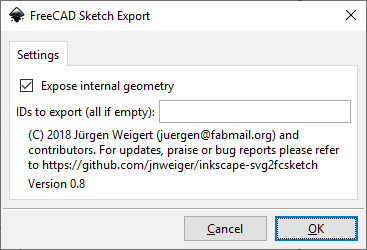
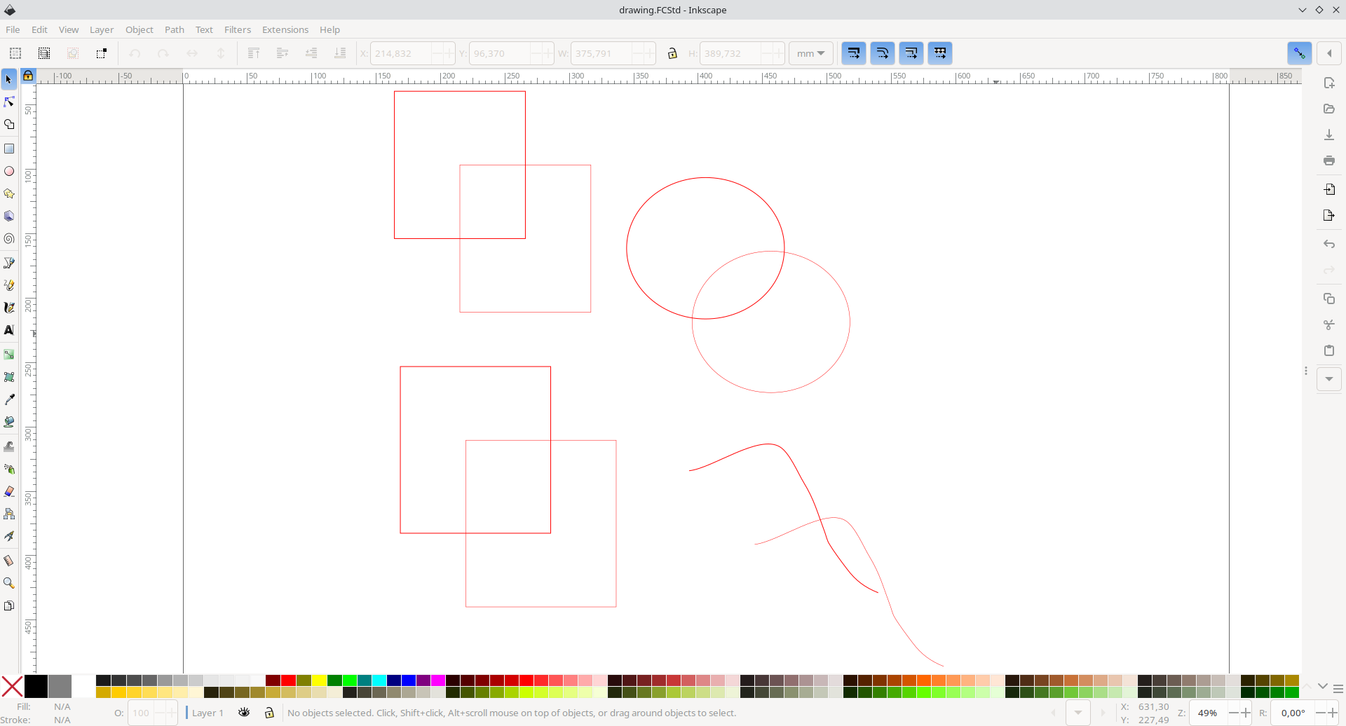
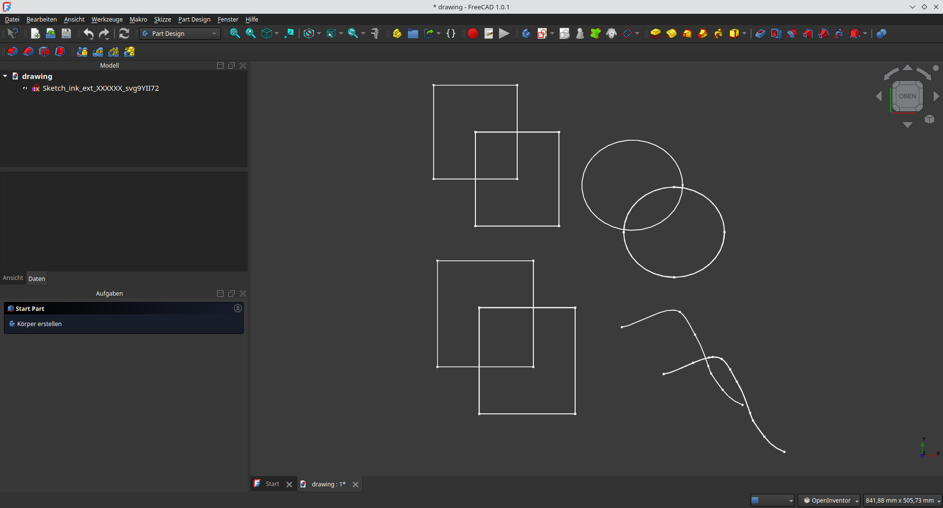
Draw some shapes and paths and save it as FCStd
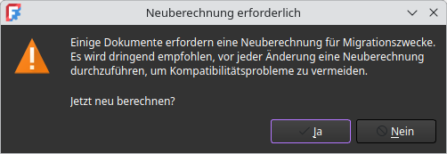
Open in FreeCAD
FreeCAD 1.X will give a warning about recalculating the file.
GCode Import
Source of documentation: https://github.com/ClayJarCom/ImportGCode
ImportGCode
An Inkscape input extension to add support for some G-code files to the File/Import... dialog.
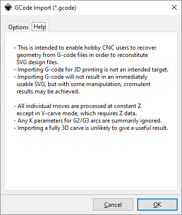
- This is intended to enable hobby CNC users to recover geometry from G-code files in order to reconstitute SVG design files.
- Importing G-code made for 3D printing is not an intended use of this extension and will likely not give cromulent results.
- This is not magic. G-code can be imported, but some manipulation will be required in order to achieve cromulence.
- Some detail (e.g. sharp inside corners) in the original design may not be reflected in the G-code. This cannot be helped, at least within the rules of this universe.
- SVG is inherently two-dimensional, so importing a fully 3D carve is unlikely to give any useful result.
Notes
- In V-carve mode, Z-axis data is used to regenerate the geometry.
- In any other mode, all moves are interpreted as being at constant Z.
- If any arcs have a K parameter, that's between them and their creator.
- In "Laser Mode", moves without the spindle on and at non-zero speed are ignored.
Reconsituting Designs from G-Code
Importing G-code is easy. Turning it back into something worthwhile may be a bit more work, but in many cases a good result can be reached without too considerable an effort.
V-Carves
First import your V-carve G-code:
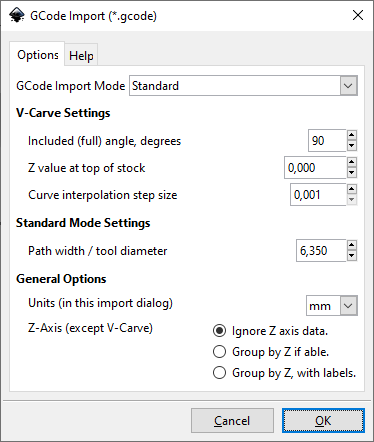
- Choose Import Mode:
V-Carve - Choose the right V-bit angle. This is the included (full) angle, so if the tip cuts a 90-degree V, enter 90, not 45.
- Using too large an angle will make everything inflate and break, and you may even get a message if it breaks the math.
- Using too small an angle will make everything deflate, and you'll end up with spikes instead of corners.
- Choose the right value for the top of your stock. Generally, this is zero, but if the G-code is zeroed to the table not the top of the stock, you'll need to enter that.
- If your V-carve G-code has G2/G3 arcs (you can open it in Notepad++ and just search for G2 and G3), you'll need to choose a curve interpolation step size. The arcs will be broken up into line segments so they can be converted into SVG path data.
Now you need to turn it back into something resembling the original geometery. For V-carves, this is actually quite easy.
- Select the import and ungroup it.
- Select some (or all) the V-carvings.
- On the
Pathmenu, chooseUnion (Ctl-+)to merge the pieces into one outline.
Standard Carves
First, import your G-code:
- Choose Import Mode:
StandardorLaser - Choose a path width / tool diameter.
- If you're going to be working with pockets and such, it's often easier to choose a small value so your imported paths show up as lines and are easier to distinguish.
- If you're importing a very basic G-code file, using the actual tool diameter may save you steps.
- Choose what to do, if anything, with Z.
- Ignoring Z often gives the cleanest results, and it is all but necessary if the G-code ramps between Z depths.
- For some G-code files, grouping by Z (with or without labels) can be a convenient way to separate pockets from profiles, et cetera.
- If you import with labeled groups and end up with a huge stack of labels, your file likely was 3D or had ramping. You may want to just ignore Z.
Unlike V-carves, there's a bit more involved when reconsituting geometry from G-code.
- First, ungroup the import, then...
- For a pocket:
- Select the set of paths representing the pocket's toolpaths.
- From the
Fill and Stroke (Ctrl-Shift-F)dialog, change the stroke width to your tool diameter. - On the
Pathmenu, chooseStroke to Path (Ctrl-Alt-C)to convert the stroke to a filled closed curve. - On the
Pathmenu, chooseUnion (Ctl-+)to turn your selection into an object with the pocket's shape. - From the
Fill and Stroke (Ctrl-Shift-F)dialog, turn off the fill and set the stroke width to a small value. - You now have an outline of the pocket.
- For an inside/outside contour cut:
- Select the paths representing the contour toolpaths.
- From the
Fill and Stroke (Ctrl-Shift-F)dialog, change the stroke width to your tool diameter. - On the
Pathmenu, chooseStroke to Path (Ctrl-Alt-C)to convert the stroke to a filled closed curve. - From the
Fill and Stroke (Ctrl-Shift-F)dialog, turn off the fill and set the stroke width to a small value. - On the
Pathmenu, chooseBreak Apart (Shift-Ctrl-K)to break the path into one inside path and one outside path. - Keep the one you want and delete the other.
- For a carve along a line in the original:
- Select the paths representing the contour toolpaths.
- That's it. If you imported with a thick path width / tool diameter, just change the stroke to a nice thin line.
GPX Import
Source of extension: https://inkscape.org/de/~mono/%E2%98%85inkgpx2svg
Get some GPX file
You can get some example files for testing this out at https://www.openstreetmap.org/traces
We use https://www.openstreetmap.org/user/jamesks/traces/3366867 for testing
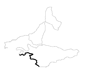
Run the extension
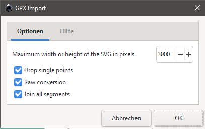
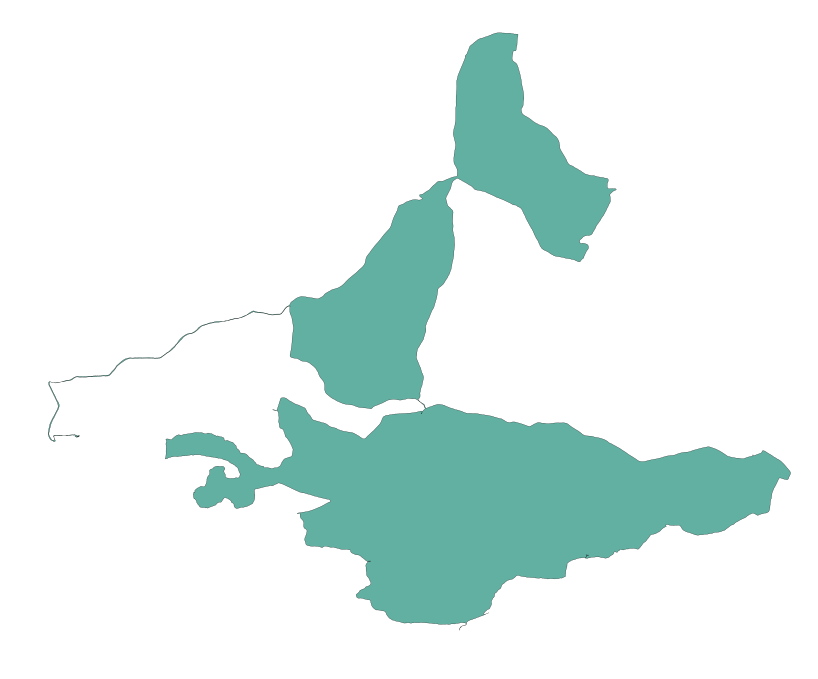
Check the result
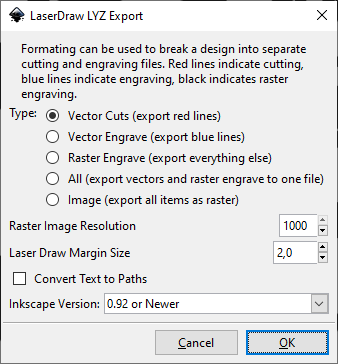
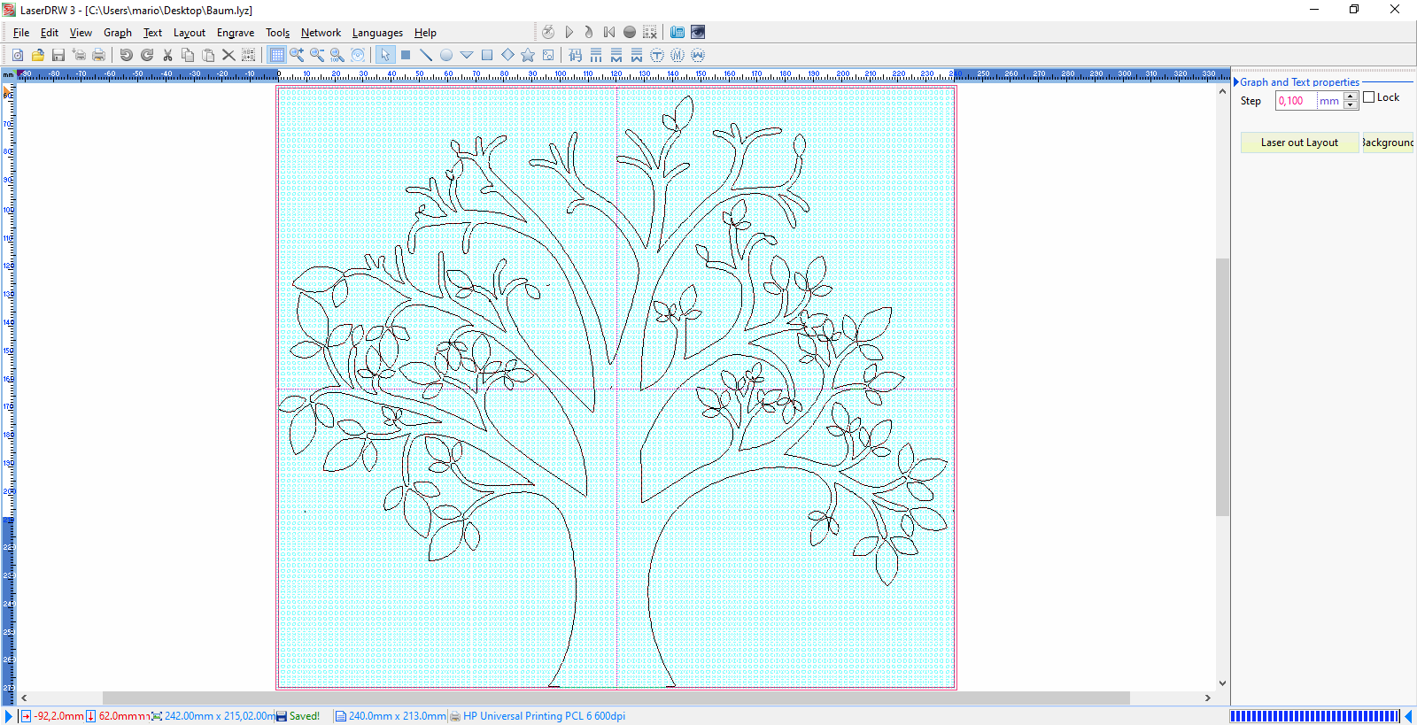
LaserDraw Export (lyz)
Source of extension: https://www.scorchworks.com/LaserDRW_extension/LaserDRW_extension-0.06.zip
Draw some stuff
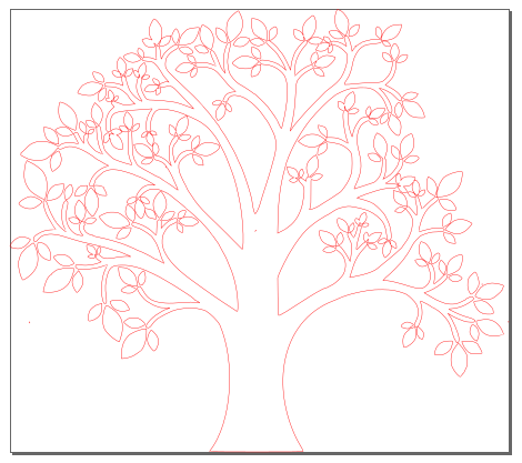
Export it
Import in LaserDRAW
LaserDraw Export (zip)
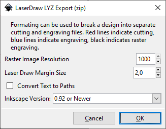
Please see LaserDraw Export (lyz) for more details about this extension
OpenSCAD cookie cutter file output
Generate a 3D-printable OpenSCAD cookie cutter file out of an Inkscape document.
Sources:
- https://inkscape.org/~arpruss/%E2%98%85openscad-cookie-cutter-file-output
- https://github.com/arpruss/gcodeplot
Instructions also available at https://www.instructables.com/3D-Printable-Cookie-Cutters-With-Inkscape-and-Open
Create SVG File
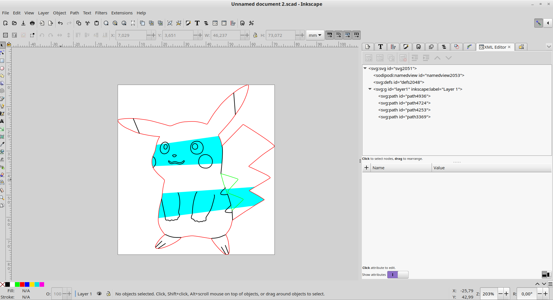
- everything converted to paths
- use red outline on outside walls
- use green outline on any inside walls (holes)
- use black outline on inside detail (this generates a wall that doesn't reach all the way through, so it marks the cookie but doesn't cut it)
- use red or green fill on areas you want filled in at full wall height
- use black fill on areas you want filled at inside detail height (walls that don't reach all the way through)
- use blue or cyan on inside connection polygons which keep inside detail and inside walls connected to the outside walls.
Load file into Inkscape. Then:
- Select all. (Ctrl + A)
- Path | Object to Path.
- Object | Ungroup.
- Remove all fill. (Click on X in color palette in lower-left corner of Inkscape screen)
- Turn on all outlines to black. (Shift-click on black square in color palette.)
- Delete duplicate lines, remove fine detail that won't work well in a cookie.
- Turn outside outline red. This should be a single polygon.
- Turn outline of any inside walls (holes) green.
- If there are any details or inside walls not connected to the outside wall, add filled-in polygons connecting the details to the outside wall. I did this by duplicating the outside walls, so I could re-use parts of their paths.
Generate 3D Files
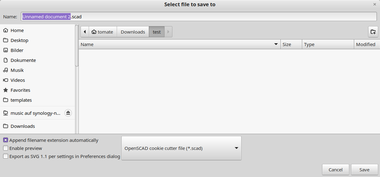
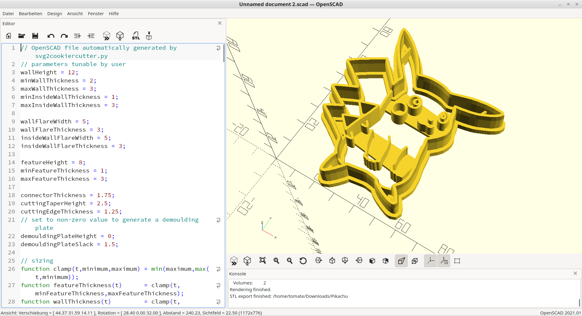
- In Inkscape, go to File | Save As... and choose "OpenSCAD cookie cutter file". Save the file. Make sure you give it a .scad extension.
- Load file into OpenSCAD.
- Adjust parameters at the top of the file to taste. The size parameter is the size of the cookie cutter in millimeters. Adjusting this will resize the cookie cutter without changing wall thickness, which is handy.
- Press the cube+hourglass icon at the top of the code to generate mesh.
- When done, press the STL button to generate an STL file.
- Print! We recommend food safe filament with 0.2mm layer size.
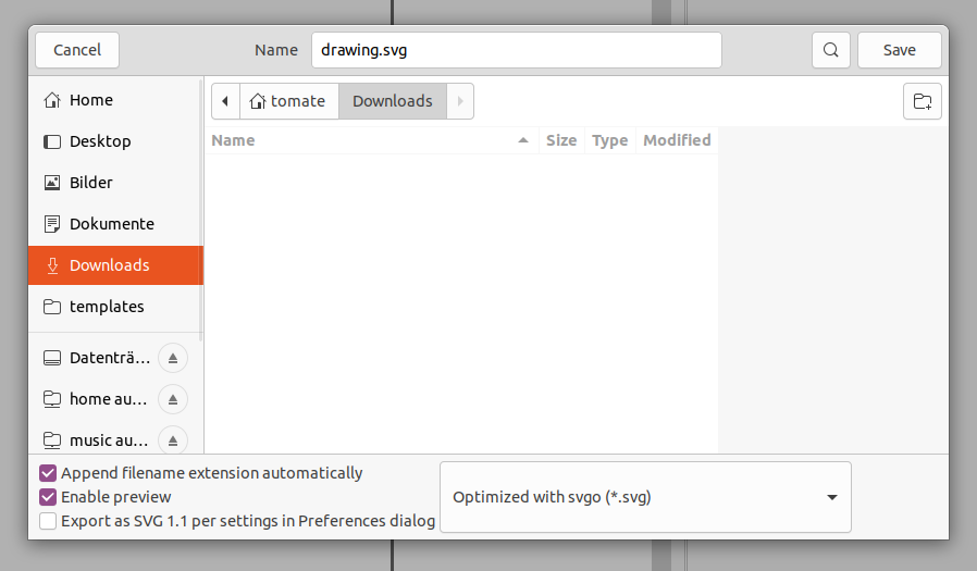
Optimized with svgo (*.svg)
Source: https://github.com/juanfran/svgo-inkscape
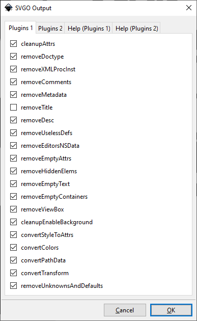
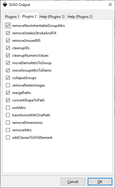
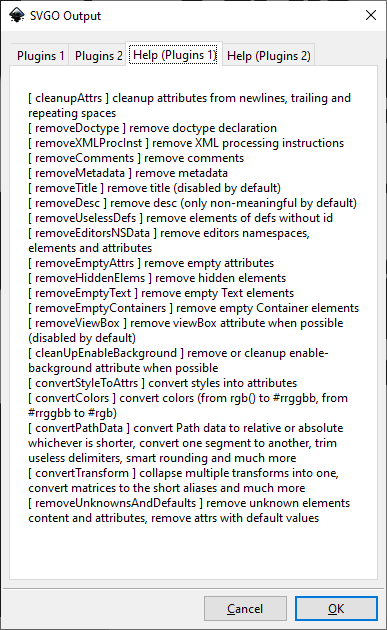
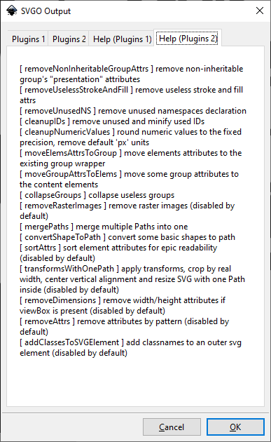
More documentation can be found at https://github.com/svg/svgo
Use this with "Save As" in "File" dialog
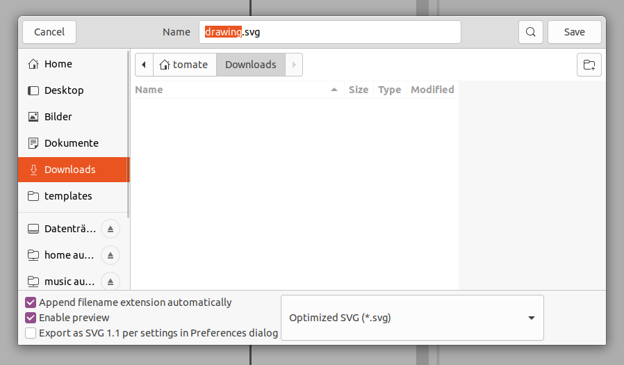
You can also use the integrated default Save As module of Inkscape to save an optimized SVG file. Inkscape has integrated support for scour
Note: There's also an extension which does the same https://github.com/konsumer/inkscape-svgo (only compatible to Linux)
Photoshop PSD (*.psd)
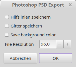
Requires gimp to be installed. The command gimp needs to be in %PATH% ($PATH)
QCAD SVG to modern DXF
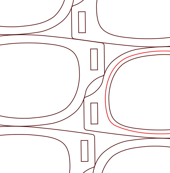
This extension uses QCAD Pro 3.X to convert an Inkscape SVG file to a nice DXF file, which has continuous polylines. It was created because the DXF12/DXF14 default export plugins of Inkscape do not allow to create proper DXF files in some manner, when it comes to more special use cases like part nesting with third party software. The rewrite of the Inkscape exporter plugins would be possible but is a complex thing to do so. As we support open source Sofware, let's use QCAD to solve it using it's powerful and easy to use libraries.
While Inkscape is not able to properly solve the polyline problem in exporting DXFs, it handles it correctly when importing DXF files, even the modern ones like DXF 2018 (R32). This was thoroughly tested though.
Warning: This extension does not work with QCAD CE (Community Edition), because it makes use of the pro's version (~40 €) advanced library functionality. So please do not make use of default installations like apt install qcad or dnf install qcad.
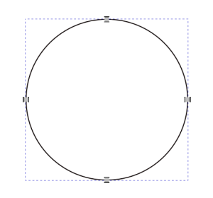
Short explanation of the issue
A default circle, converted to a path, looks like this in Inkscape:
Exported to DXF 14 and reimported to Inkscape looks like this:
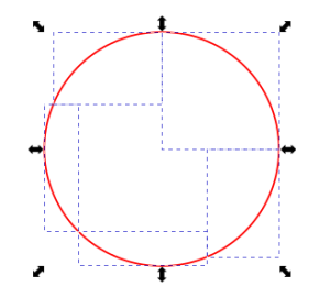
It comes as a group, but not as a single path.
Color misinterpretion
Using OpenDesign DXF library from QCAD, we get wrong colors. Black gets brown or blue for example. The reason is not known. So we use the builtin DXF R15 by dxflib by default. This supports correct color set.
How to use the extension
Buy and install QCAD Pro by downloading it from the provided installation source URL (this info is received after payment).
#install qcad as regular user
chmod +x *.run
./qcad-3.28.2-pro-linux-x86_64.run
Then you can use the extension from GUI to export SVG to QCAD/DXF
Manual process
The following script is used to convert SVG to proper DXF:
To make this work, ensure QCAD is not already running.
vim polify-dxf.jsinclude("scripts/ImportExport/SvgImporter/SvgImporter.js")
include("scripts/Pro/Draw/Polyline/PolylineFromSelection/PolylineFromSelection.js");
include("scripts/ImportExport/SvgImporter/SvgImporterInit.js");
RFileImporterRegistry.registerFileImporter(new SvgImporterFactory());
qApp.applicationName = "MyApplication";
var storage = new RMemoryStorage();
var spatialIndex = new RSpatialIndexSimple();
var document = new RDocument(storage, spatialIndex);
var di = new RDocumentInterface(document);
const importer = new SvgImporter(document);
di.importFile("/home/tomate/Downloads/DXF-Test.svg");
di.selectAll();
var tolerance = 0.001;
PolylineFromSelection.autoJoinSegments(di, tolerance);
//use legacy dxflib to have correct colors. using the export of "OpenDesign" modify original colors, like black #000000 is getting #00004C or sth. like this
//di.exportFile("/home/tomate/Downloads/DXF-Test.svg.dxf", "R32 DXF");
di.exportFile("/home/tomate/Downloads/DXF-Test.svg.dxf", "dxflib");/home/himbeere/opt/qcad-3.28.2-trial-linux-qt5.14-x86_64/qcad -autostart polify-dxf.js > /dev/null 2>&1See also https://qcad.org/rsforum/viewtopic.php?t=8471
Roland CutStudio *.eps Export
See Open in Roland CutStudio. This extension does the same export but it will not call CutStudio. Instead it will save an importable *.eps file to the selected target directory by export menu.
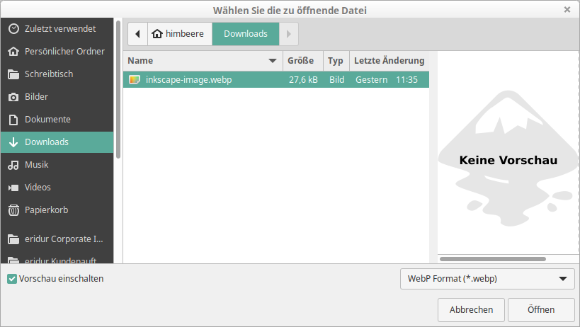
WebP Import
Import *.webp image files using ImageMagick conversion. Routine is webp → png → svg → write into Inkscape canvas.
You need to install ImageMagick. The command magick or convert needs to be in path variable, otherwise the extension will fail.
Fedora:
sudo dnf install ImageMagickUbuntu:
sudo dnf install imagemagickWindows:
https://imagemagick.org/script/download.php#windows
Add the binary folder to %PATH%
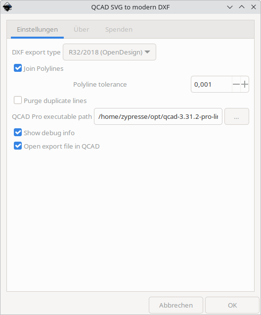
Example Dialog