Transformations
- Another Perspective
- Apply Transformations
- Barrel Distortion
- Bezier Envelope
- Cutting Optimizer (Nesting)
- Epilog Dashboard BBox Adjust
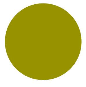
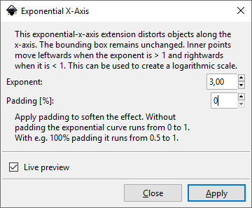
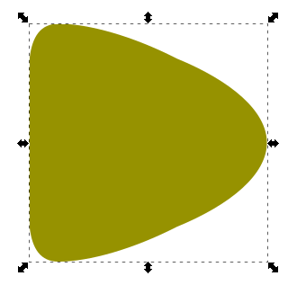
- Exponential Distort
- Flip
- Inset Alignment
- Isometric Projection
- Mirror
- Normalize Drawing Scale
- Parallel Translation
- Raster Perspective
- Rotations - Minimum Bounding Box Area / Minimum Width / Find All Optimal
- Scale To Path Length
- Scale To Real
- Scale To Size (Replaced by default transform scale)
- Set View Box (Replaced by CTRL + SHIFT + R)
Another Perspective
This is similar to Bezier Envelope
Draw an object and convert to path

Draw some envelope path
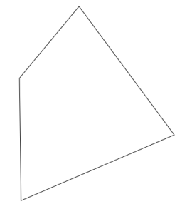
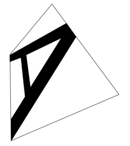
Run the extension and check result
Apply Transformations
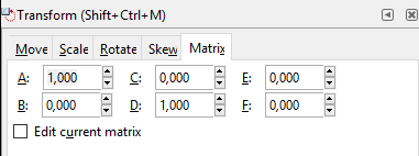
An Inkscape extension which recursively applies transformations to shapes. This will remove applied Matrix values from object but will keep it's transformation. It will reset the matrix to basic values like these:
It will also clean Live Path Effects
Barrel Distortion
Draw some shape
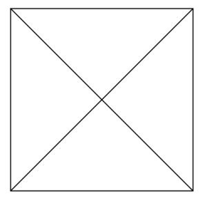
Run the extension
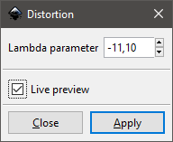
Result

Bezier Envelope
This extension is similar to default Inkscape extension "Modify Path → Envelope" and is also similar to Another Perspective.
Note: this extension does not work for svg:circle which were converted to svg:path. Those will contain a or A commands in their path. We need to convert those to paths with c or C commands!
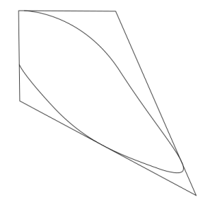
Draw the path you want to fit into the envelope
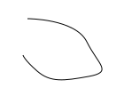
Draw your 4-sided envelope around
Please note!
- Paths with more than 4 sides will not correctly apply. Paths with less than 4 sides will fail. So just draw a square shape (angles don't have to be 90 degrees)
- Start in the upper left corner and draw clockwise. Otherwise your result may get twisted in an undesired way
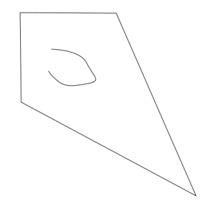
Run the extension
First select the inner path. As second select the envelope. If you dismiss the order the extension will fail.
Cutting Optimizer (Nesting)
Source of documentation: https://translate.google.com/translate?hl=de&sl=fr&tl=en&u=https%3A%2F%2Fwiki.fablab-lannion.org%2Findex.php%3Ftitle%3DCutOptim
CutOptim
Presentation
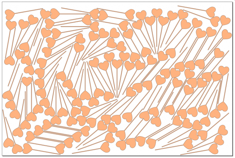
All the users of the laser cutter have probably been confronted with the problem: my drawing does not fit in the wood sheet at my disposal or even in the laser cutter! To try to remedy this problem, I started writing an optimization program for placing objects on a sheet.
For interested readers, this is a variant of a problem well known in the world of optimization (bin packing problem). By doing a little research on the Web, there are also many links to programs performing this task, but the free versions are often very limited, they are content to optimize the cutting of rectangles. This can help a furniture manufacturer, but it's too limiting for a laser cutter!
This program reads an input SVG file containing the objects to be placed and outputs a second SVG file containing the placed objects.
It can be used as is (command line, no GUI!) Or as an extension inkscape which then provides the GUI.
Environment
As mentioned above, this program can be used alone or as an inkscape extension.
The work to be done can take a relatively long time, it is better to run it on a modern processor, but if you are in no hurry ...
The memory consumption is reasonable, no need to rush to buy new RAMs!
Software
First of all as it is a program written in C ++ for a performance issue, it must be compiled on your machine.
I wrote this program under Linux / Ubuntu (compiled with gcc), but since there is no system dependency, it should work as it is under any other version of Linux. For fans of Windows (there is!), I created a Visual Studio project that allows to compile on this platform. For Mac users, sorry I do not have it, you will have to fend for yourself, but the C ++ used is really standard, it should work as soon as you have access to a compiler. For information, I did not change the code between Linux and Windows, that's saying!
Linux installation
The code is available here: https://github.com/thierry7100/CutOptim For the uninitiated, you clone (or download) the directory, it comes in the form of a .zip archive, which must be extracted. Then you open a terminal, go to the created directory and launch the commands:
- make release
- make install: this will copy the software to the directory ~ / .local / bin which is in the list of executable directories, which will allow you to use it directly (this may be specific Ubuntu, it's up to you put the program elsewhere on another system.
- make install_inkscape: this will copy the program to the inkscape extension directory (~ / .config / inkscape / extensions). If you want to make this extension available for all accounts on your machine, copy the file cutoptim.inx + the executable into / usr / share / inkscape / extensions (you must be root).
If you have opted for the inkscape extension, at the next start you will have a Fablab / Laser Cutting Optimizer extension
cd ~
git clone https://github.com/thierry7100/CutOptim.git
cd CutOptim
make release
#make install

#try
~/CutOptim/bin/Release/CutOptim
Windows installation
The code is available here: https://github.com/thierry7100/CutOptim.
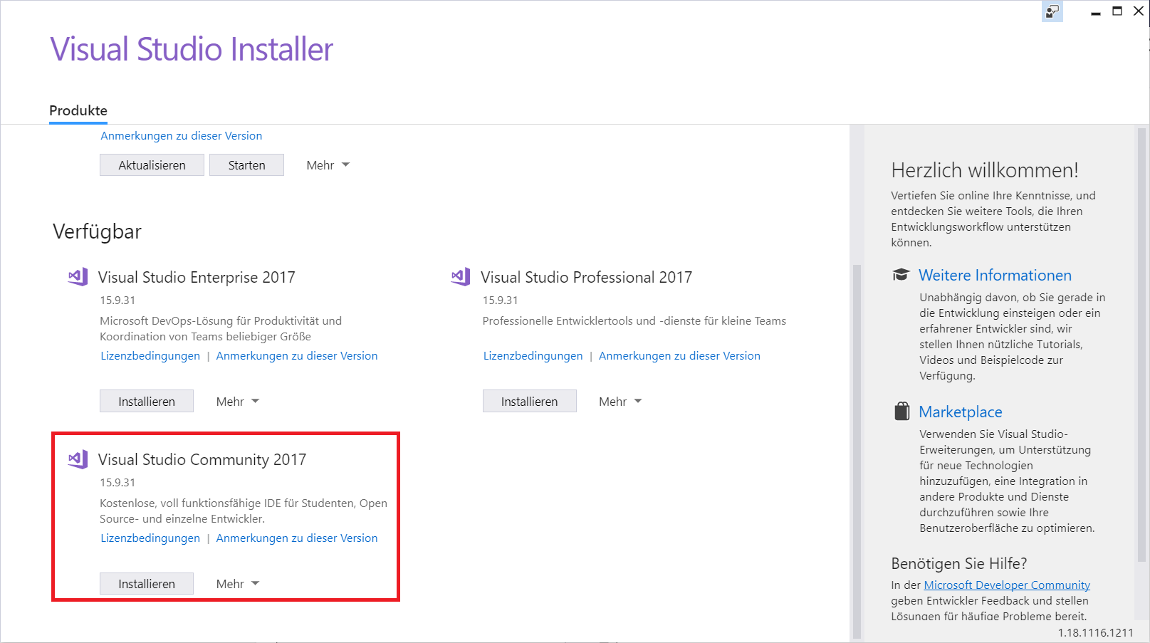
For the uninitiated, you clone (or download) the directory, it comes in the form of a .zip archive, which must be extracted. Then you launch Visual Studio, you can get a free version for special purposes, see Visual Studio Community Edition v17 (You also need to install Windows SDK-Version 10.0.16299.0 within Visual Studio Installer).
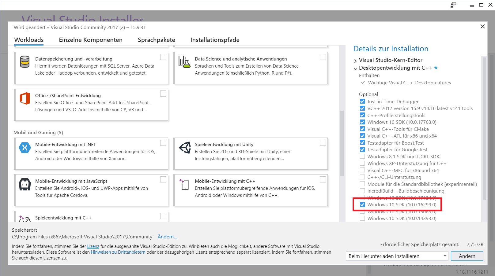
Then, once Visual studio started, you have the CutOptim project, then:
- You ask to generate the release version of the project if it is not the one that appears in the menu bar.
- You choose the platform (x86 or x64) of your choice. By default the file is configured in x64, if you have a 32bit version of Windows, change to x86.
- You click Generate / Generate Solution, the compilation starts and after a few seconds, your program is available.
- Then, under windows, better use this program as extension inkscape, the command line is hardly used? ! To do this, copy the cutoptim.inx and CutOptm / x64 / Release / CutOptim.exe files to the inkscape extensions directory. This can be found via the Edit / Preferences / System command, but it is usually under C: \ USERS \ <Your user name> \ AppData \ Roaming / inkscape / extensions. Attention, to see this directory, you will have to validate the visualization of hidden files under the explorer of files, if it were not done.
As in Linux, at the next start of inkscape you will have a Fablab / Laser Cutting Optimizer extension
Operation
The input and output format of the files is the SVG format, available on many software programs. If you use inkscape, it is the native format, the program has been tested in this context. It should also work with files from other drawing software that generates SVG. If you have a problem tell me (thierry@fablab-lannion.org)
Description of the process:
- The inkscape document (at least its size) can usually be of importance, here it sets the size of the sheet used for cutting. You will need to set a document size compatible with your material (and the cutter, of course!).
- First of all, the program reads the inkscape document, it only considers paths or simple objects. The texts not transformed in the way, the images ... are ignored. I therefore advise to turn everything into a path before launching the program. Inkscape Ctrl + A then Objects in Path (SHIFT + Ctrl + C). Unclosed paths are also ingnorated, the software is only able to process shapes with a closed outline.
- Paths can be placed anywhere, in the sheet or out, it does not matter. To a certain extent, they can even be superimposed (see below).
- Then, from these paths, the program creates polygons approaching the paths (with an error of less than 0.1mm on average).
- Then the program "enlarges" these polygons to prevent paths from touching each other in the final result. The size of the enlargement is configurable.
- The program then takes these enlarged polygons and will try to place them in a way that is not optimal but good. Why not optimal because the problem is difficult (complete NP in mathematical terms) and requires a very long time even for simple configurations. The basic idea here is to start from the largest polygon, then to place the sorted polygons by decreasing size such that a vertex of the polygon to be placed is positioned on a vertex of an already placed polygon. This reduces the space of possibilities, even if it remains very large!
- The "best" configuration is obtained when the size of the convex hull is minimal. Another mathematical term! The convex hull is the smallest convex hull containing all points of all plotted polygons. Intuitively, this maximizes the free space on the plate, which is the desired result. Be careful, it is not necessarily the smallest rectangle, the convex envelope is not usually a rectangle!
- To place the paths, the software is allowed to turn the objects, unless you block this possibility. Depending on your needs (non-homogeneous material) you may have to limit rotations to 0 and 180 ° for example, or even to block any rotation (this will be the case for example with printed fabric).
Program Options under inkscape
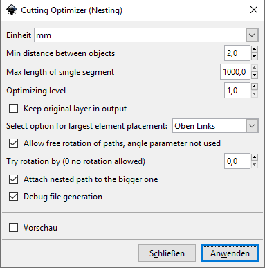
The program has many options detailed below:
- Units: Always use the mm, the program is not tested for other choices.
- Min distance between objects: This is the size of which polygons will be enlarged. This value must be greater than 0.8mm, the approximation by polygons is not perfect.
- Max length of single segment: as explained above the software will try to find a good configuration by positioning vertices on other vertices. It can be interesting in some cases to "add" vertices to have more possibilities. If an edge is larger than the specified size, it will be broken into multiple segments, with additional vertices. Do not abuse this option, too low a value will slow down the treatment tremendously. Do not go below 100mm in most cases, even if the value 0 is allowed to indicate that you do NOT want to use this possibility.
- Optimizing level: as indicated above the program places the polygons in order of decreasing size (we place the largest pebbles first ...). This sometimes leads to clearly suboptimal situations. By increasing this parameter, the software will optimize the placement of a group of N polygons. This gives better results, but be careful, it considerably increases the treatment time. Do not exceed 2 or 3, if the default value of 1 does not give good results. If you draw has 300 vertices already placed (rather low value actually) and you allow rotations in steps of 10 °, use N = 2 will multiply operations by 36 * 300! And for N = 3 by (36 * 300) ²!
- Keep original layer in output. If you do not trust!, You can check this option, the original shapes will be kept as well as those placed, but placed in different layers. You will be able to check the work done.
- Select option for largest element placement. The first item can be placed where you want on the page. Usually at the top left, but the center also gives good results.
- If this option is checked, the rotation angle of each object will be chosen from 4 to make the edge coincide with one of the two of the vertex on which the object is going. to be positioned. This option is economical in processing time (at most 4 tests) but can give less good results than the fixing of the angle of rotation. The results are worse when the segments are very short, if the input form is not a polygon for example.
- Try rotation by (0 no rotation allowed): This option is incompatible with the previous one, it is only valid if the previous option is NOT checked. In this case, the objects are positioned on discrete rotation steps. 0 means that rotations are prohibited, this is useful when the material is not homogeneous. For MDF, no restrictions, but for wood or even plywood, if you want to respect the direction of the wood, rotations are not advisable. Choose 180 ° in this case. Attention, low values greatly increase the calculation time. With 10 °, there are 36 times more calculations than with 0 °! If the input shapes are rectangular, a value of 90 ° gives good results.
- In practice, we often deal with situations or related objects. For example, a plate with fixing holes. If this box is checked, the software checks if the path is included in another one, and if it is, it will not process it but link it to the larger path. Once it is placed, the same transformation (rotation / translation) will be applied to the "small" included object. Attention the software is not able to recover the space released in holes, you have to leave a little work anyway.
- Debug file generation: If this box is checked, a debug file (Debug_CutOptim.txt) is created in the inkscape extension directory. This can be used to understand what has (badly) happened.
Program options via the command line
The software has pretty much the same options as via inkscape, with some additions.
eridur-cutoptim.exe [OPTION...] [optional args]

  -f, --file SVG Input File     File (default: TestPoly1.svg)
  -o, --output SVG Output File  Output file
      --positional arg          File to be processed
  -h, --help                    Print help
  -d, --distance 1.0            Min distance between paths to be cut
  -m, --max_length 1000.0       Max length of one segment, break than longer
  -l, --optimizing_level 1      Optimizing level, process list_size elements together
      --debug_level 0           Level of debug info in specific debug file
      --debug_file              Generate debug info from inkscape (default: true)
  -k, --original                Output Original layer
  -n, --nested                  Keep nested path together (default: true)
  -y, --layer_output 0          Output internal layers : 1 Input layer, 2 Polygon, 4 Large polygon, 8 Hull layer, 16 Placed Polygon layer, OR these values to output multiple layers
  -a, --angle 90.0              Rotation step
  -r, --free_rot                allow free rotation (default: true)
  -p, --firstpos Position of largest object on the sheet
                                Position of largest object
Possible developments / known limitations
- No doubt a lot of things, to you to propose and even to realize, the code is open!
- the colors and layers of the objects do not play a role yet
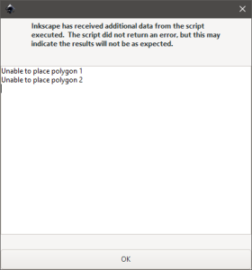
- generates trashy results in a lot of situations
- there is no solution to remove duplicate edges
- there is no solution to allow zero distance between the parts
- known Bugs:
-
does not work for parts which have lines it it (groups with things like living hinge flex pattern) and ignores groups of objects
-
| Example | Input | Output |
| 1 |
|
|
| 2 |
|
|
| 3 |
|
|
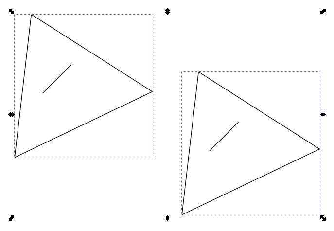
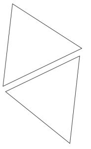
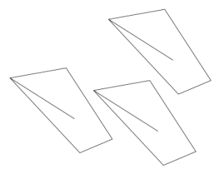
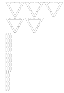
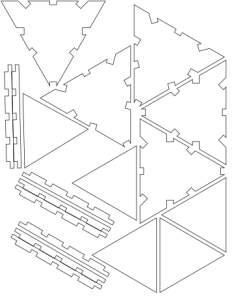
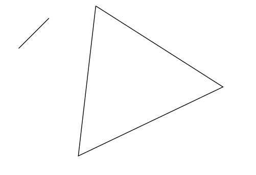
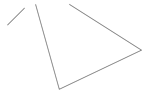
as soon as you have more than one open path (e.g. a line with 2 points) CutOptim will crash
| is okay (open contour will be deleted while nesting) | will crash |
 |
 |
Bibliography
As indicated the subject is well known in the scientific world, I used the two following articles
- Waste minimization in irregular stock cutting published in 2014 by Doraid Dalalah, Samir Khrais and Khaled Bataineh. This article gives the basis of what is achieved.
- Jostle heuristics for the 2D-irregular shapes bin packing problems with free rotation published in 2018 by Ranga P. Abeysooriya, Julia A. Bennell and Antonio Martinez-Sykora
Good reading !
Epilog Dashboard BBox Adjust
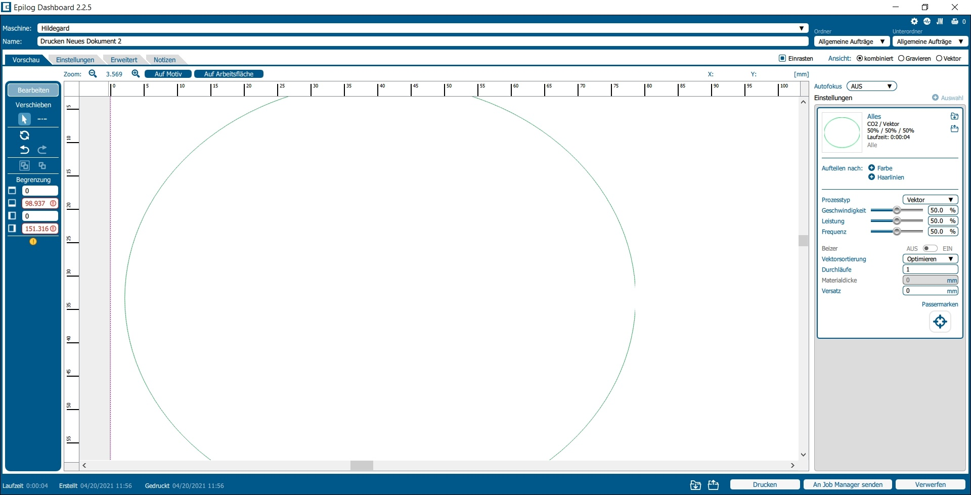
This tool is a helper to adjust the document border including an offset value, which is added. Sending vector data to Epilog Dashboard often results in trimmed paths. This leads to wrong geometry where the laser misses to cut them. So we add a default (small) amount of to expand the document's canvas.
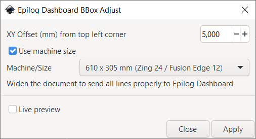
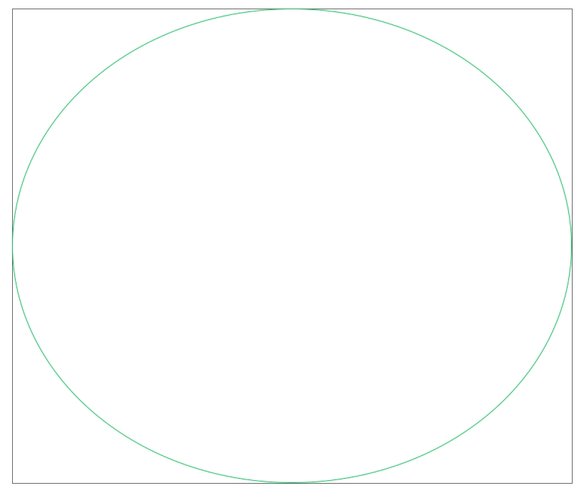
The issue in pictures
| Correct fit in Inkscape | Import in Epilog Dashboard (ellipse lost parts of its contour) |
 |
 |
Exponential Distort
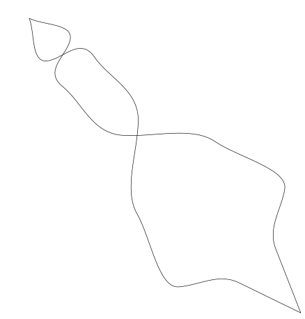
Flip
This extension only operates on a single path (or a selection of paths, but all individually) by flipping it about the imaginary line that goes from the paths first node to its last node.
Source: https://github.com/aconz2/inkscape-extension-flip
Draw some path
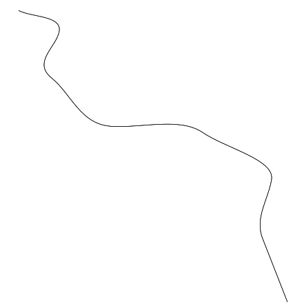
Run the extension and check result
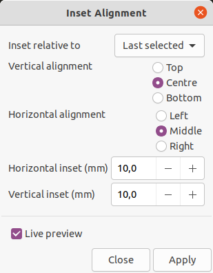
Inset Alignment
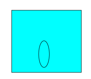
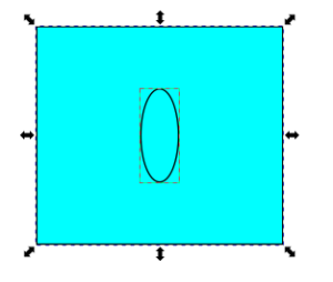
This extension aligns elements into the first, last or largest selected item. The bounding box shape and some custom entered offset values are used to calculate the new position.
Draw some objects
Run the extension
Isometric Projection
Source of documentation: https://github.com/jdhoek/inkscape-isometric-projection
http://jeroenhoek.nl/articles/svg-and-isometric-projection.html
This extension has two modes (dimetric and isometric)
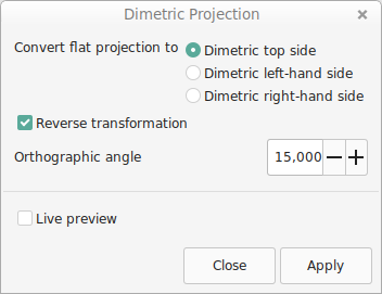
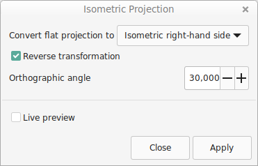
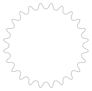
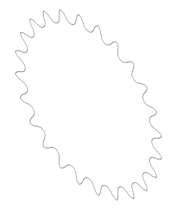
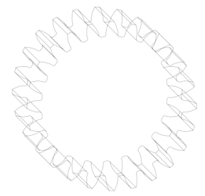
Also have a look at Live Path Effect "Extrude" for projections:
Mirror
This function is a legacy one because the exact same can be done with Live Path Effects ("Mirror symmetry")
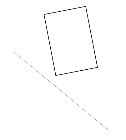
Draw some objects and a path (line) to mirror
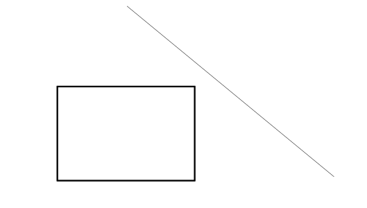
Make a copy of the objects you want to mirror (otherwise the tool will just move the selection)
Use Ctrl +D
Run the extension
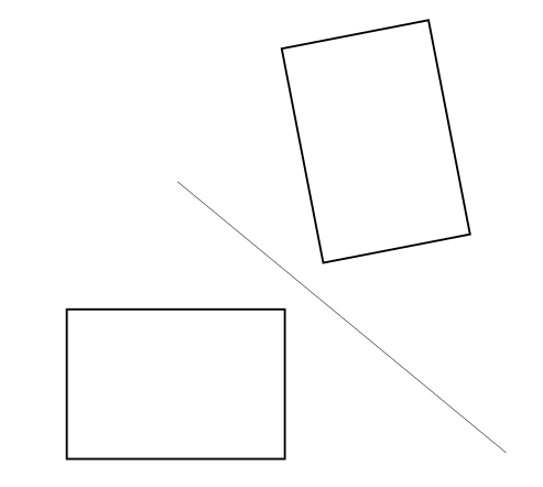
If you forget to make a copy:
Normalize Drawing Scale
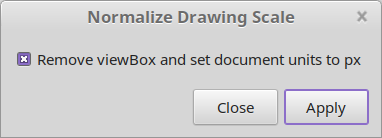
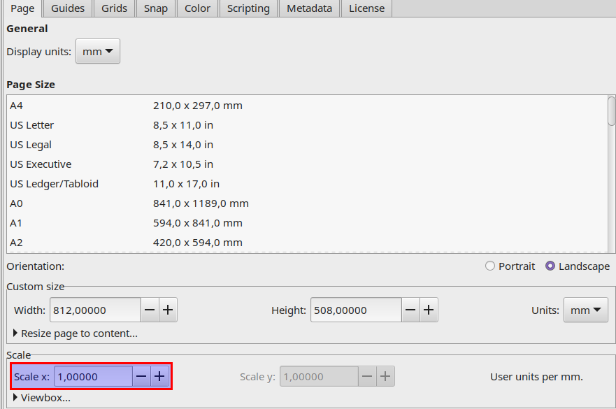
This extension will set the drawing scale to 100% and adds fitting transforms to keep the element size. You can use Apply Transformations to apply those transforms afterwards. This neat toolchain helps to handle all path command coordinates easier. Especially helpful for import/export usage for programs which might not handle viewBox of svg:svg head correctly.
Parallel Translation
Source: https://github.com/chris0371/parallel-translation_extension
Allows parallel translations and alignment operations of selected straight lines.
These lines can be simple path objects (with only start- and end-node) or line segments of larger path objects.
Purpose
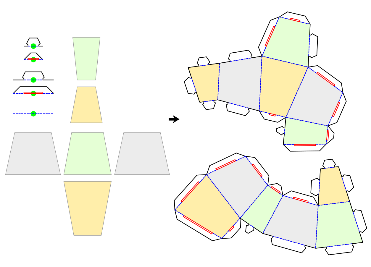
This extension has been written to help making a strange kind of paper cube with angles different to 90 degrees. It helps to align the faces together (probably in different arrangements, as indicated in the right side of the screenshot below) and to add complex folding flaps with lines in different colors to the edges. There are options to resize the length of the flaps so that they match the length of the edges.
More detailed description
The functionality of the extension is spread across different tabs of the UI. The currently selected tab determines what functionality is performed by the extension. At first glance, the individual tabs seem to have completely different functionality, but if you look closer, it all comes back to the same basic concept.
You have to tell the extension what object(s) of your drawing to use/modify by selecting them before hitting the apply-button.
Object types to select
Within all the objects selected by you, the extension always looks for a line segment, calculates its orientation angle and length, and performs some tasks based on that calculation. This line segment could be
- a simple path object with just the start- and end-node. In such a case, you just have to select the whole path object. Or it could be
- a line between two nodes of a larger path object. In that case, you have to select the two nodes of the path.
For the "Group-Alignment" functionality, the extension also looks for an alignment group. This is a group of an arbitrary number of other objects, which is aligned to the line segment we've talked about earlier. 'Aligned' means that the group is rotated, moved, and it's width is modified to match the position, orientation and length of the line segment.
The extension assumes two things about an alignment group:
- The group shall be in its horizontal default orientation. That means that if this group is to be aligned to a horizontal line segment drawn from left to right, it does not need to be rotated.
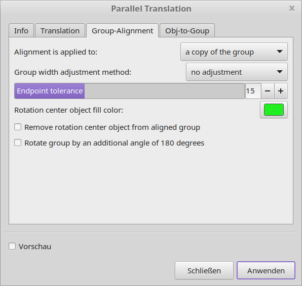
- The group shall contain exactly one special object which center marks the rotation center of the whole group. It is recommended to use a circle or square or simple path for this. The extension identifies this special object by its fill-color. The color to look for can be set in the UI (at the "Group-Alignment"-tab) and defaults to neon green (#0x00FF00)
Information Tab
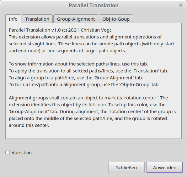
This first tab contains version information and a brief explanation of extensions functionality. Hitting the 'Apply'-button in here will just show some basic information about the drawing, what objects are selected, and some basic calculations done on those objects (like length and orientation angle for the selected line segment(s).
Translation Tab
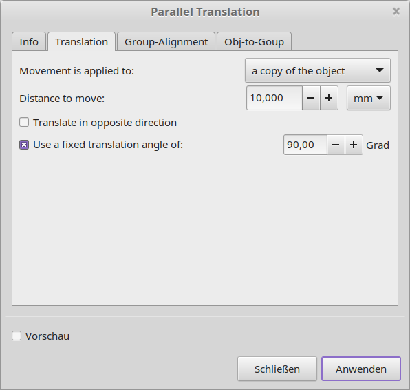
This tab performs parallel translation of the selected line segment. That is, the extension calculates the orientation angle of the selected line segment, and moves the object by the given distance in the direction of a right angle to the lines direction.
There are options to apply the movement to just the original object, to the original object and leaving a copy at the original position, or to a copy of the object leaving the original one untouched.
There are also options to revert the movement direction and to use a fixed translation angle instead of calculating it from the original line orientation.
Group-Alignment Tab
This tab aligns the selected group to the selected line-segment. 'Aligned' means that the group is rotated, moved, and it's width is modified to match the position, orientation and length of the line segment.
There are options to apply the alignment to just the original group, to the original group and leaving a copy at the original position, or to a copy of the group leaving the original one untouched. Further, there are different options to adjust the width of the aligned group.
There are also options to apply an additional rotation of 180 degrees to the group and to auto-remove the group rotation center object from the aligned group.
For the strange-paper-cube example, this functionality can be used to place the folding flaps at the straight but odd-angeled edges of the faces.
Object-to-Group Tab
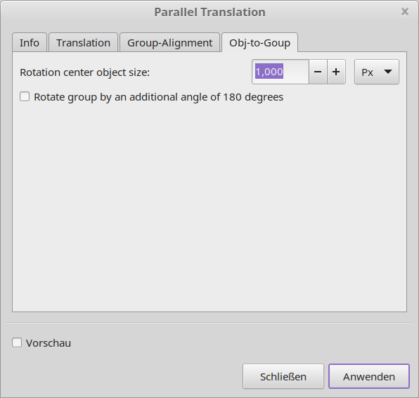
This tab is used to turn an ordinary object into an alignment group. This is done by rotating the object so that the selected line-segment is in horizontal orientation, adding a group rotation center object at the middle of the selected line-segment, and then group the objects together.
For the strange-paper-cube example, this functionality can be used to align the faces of the cube together. Moving and rotating face A to align one of its edges with the corresponding edge of a fixed face B would be a 2-step-process like this:
- Select the line-segment to be aligned from face A and turn the object that makes up the face into an alignment group using the Object-to-Group tab.
- Select this group and the line-segment to be aligned with from face B. Then align just this group (no copies) using the Group-Alignment tab with no group width adjustment.
Raster Perspective
Source: https://github.com/s1291/InkRasterPerspective
Apply a perspective transformation to bitmap image using the selected path as envelope, without the need to use an external software to transform the image. Select the raster image and the quadrangle path (envelope).
Rotations - Minimum Bounding Box Area / Minimum Width / Find All Optimal
There are three extension from https://github.com/hobzcalvin/LaserPrep which allow optimal rotation according to width or bounding box.
Rotate for Minimum Width
Helpful when trying to nest objects, this extension rotates all selected objects to minimize their width.
Rotate for Minimum Bounding Box Area
Similarly, this rotates all selected objects to minimize the area of their bounding boxes.
Find All Optimal Rotations
This rotates the selected objects to minimize the width and area of their bounding boxes. If these are optimized at different angles, the objects are duplicated and rotated accordingly.
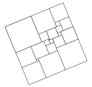
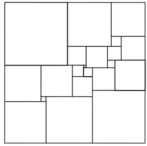
Having some rotated object(s)
Run the extension
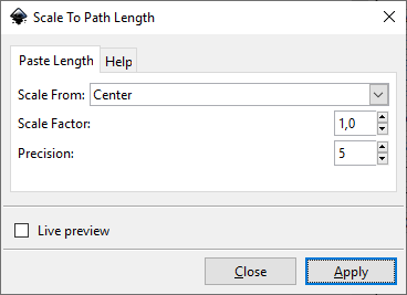
Scale To Path Length
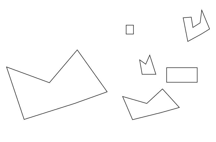
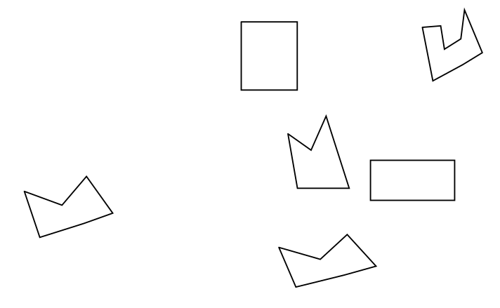
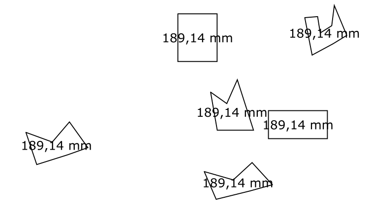
This effect makes the length of all the destination paths the same as that of the source path, while maintaining their shapes. The source is the topmost path in the selection.
Please note if the size seems incorrect after running this extension, please check if you have left some transformations. They can be removed by Apply Transformations.
Draw some paths
Measure to check
Visualize Path → Measure Path
See also
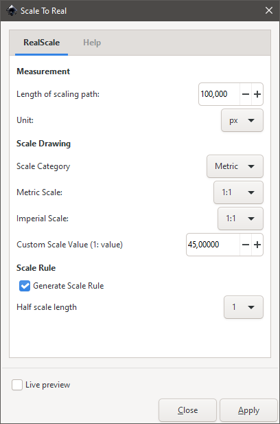
Scale To Real
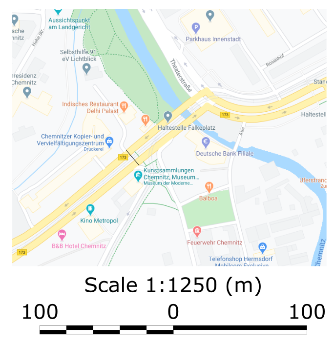
Good description for this plugin can be found at the source → https://gitlab.com/Moini/inkscape-realscale-extension
See also
Scale To Size (Replaced by default transform scale)
Draw some objects / paths
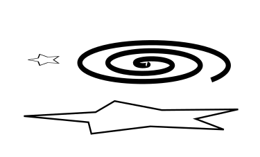
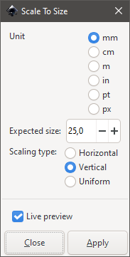
Get the result
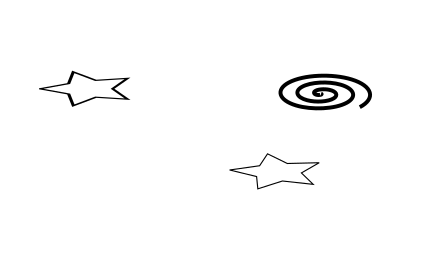
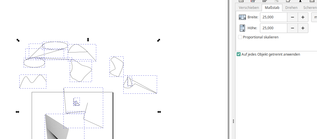
This extension is obsolete because we can do the same with default transformation menu:
See also
Set View Box (Replaced by CTRL + SHIFT + R)
This plugins allows to adjust the view box (canvas) size according to a drawn rectangle. You can do this using CTRL +D too but it might be quicker sometimes using "Set View Box". Use the built-in default key combination to quickly resize the view to the selected object (CTRL + SHIFT + R).